![]()
Application Note #791Revision AJuly 2021
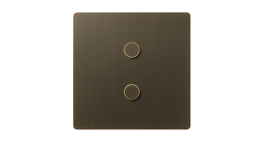
Alisse Keypads – Round Backbox Installation Best Practices
OverviewOnce installed, the Alisse keypad is a beautiful wall control designed to be elegant and discreet. To ensure the best installation possible, this document outlines the international Alisse keypad installation best practices.
Backbox Selection
Many backboxes are well-suited to be used for Alisse installations with some exceptions. To ensure that the keypad’s adapter will be able to cover the backbox and its installation, the backboxes used for one-column, two-column, and three-column units should have a diameter of 75 mm (3 in). In order to ensure spacing exists for the connector and wiring, the depth of any backbox should be greater than 35 mm (1.4 in). Alisse keypads ship with a special QS connector that allows them to be installed in a 35 mm (1.4 in) deep backbox. Using a standard QS connector requires a deeper backbox.
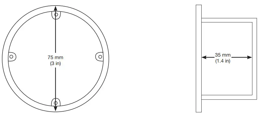
Figure 1: Visual depiction of backbox size limitations.
International Style Round Wallbox:Screw Spacing: 60.3 mm (2.4 in) (red arrows)Recommended Lutron Part Number:EBB-1-RD*EBB-15-RD*
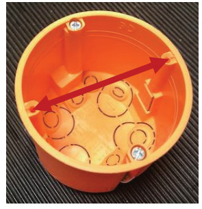
* Please reference page 9 for information on other manufacturer’s backboxes.
Wall Inspection and Preparation
One of the most important factors to consider in any Alisse installation is the flatness of the wall. A non-flat wall could be caused by various factors that include decorative wall coverings (tile, stone, etc.), plaster not evenly applied, plasterboard spackle applied but not sanded evenly, etc. This non-flat wall could create a gap between the adapter and wall or the faceplate and adapter. If the gap is too large, the snaps in one or more corners may disengage which will cause rocking, or in some extreme cases, the unit will not be able to be installed into the adapter or may disengage over time.To confirm the wall you are working on is flat, we recommend using a straight edge and holding it against the wall at the desired installation location, as shown in the photo below. There should be no visible gap between the straight edge and the wall in the area of your installation. We recommend checking flatness in both the horizontal and vertical directions.
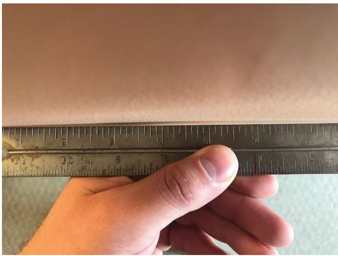
Photo of straight edge used to evaluate wall flatness.
Cutting Holes in Wall
Debris or burrs left from hole construction can cause gaps to exist between the wall and the Alisse keypad.
Before and after photos of debris and burr created during a dry-lined wall installation.
Example of an installation with a flat wall and deburred hole.
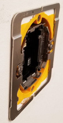
Backbox Installation
Prepare the wall and backbox hole as described in the previous sections. Install the backbox to ensure it is as flat and flush to the wall as possible. The goal of this installation is to ensure that the unit cannot shift on the wall under normal use while minimizing the gap between the wall and the adapter.
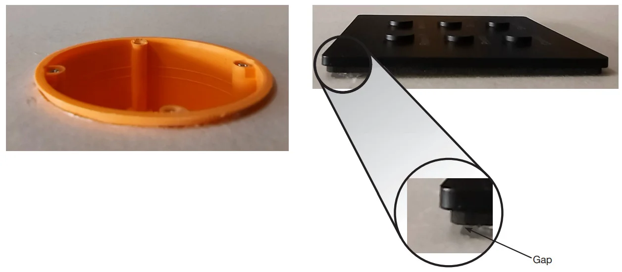
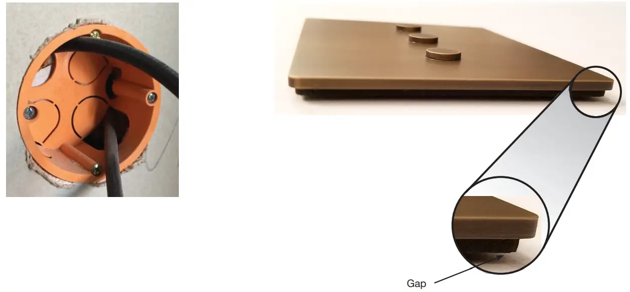
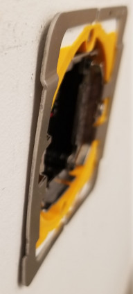
Example of a protruding backbox and its impact on the keypad.
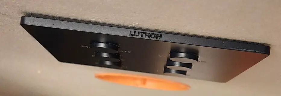
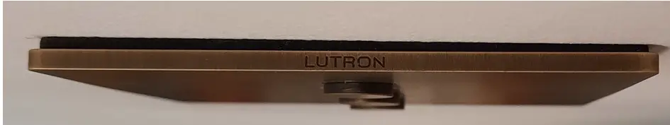
Example of an installation with a flat wall and flush-mounted backbox.
Mounting Screws
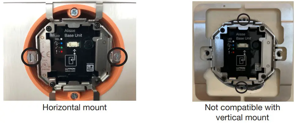
The Alisse keypad must be mounted using the horizontal (left/right) screw holes. It cannot be mounted using the vertical screw holes (if present), on your backbox.
The backbox must be installed horizontally with the mounting screws being as level as possible.
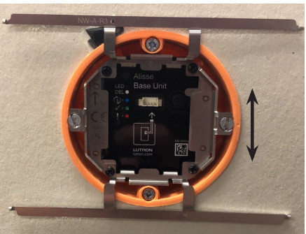
The backbox is mounted slightly rotated. The mounting screws are not level, therefore, the keypad will not be level.There is limited adjustability in the adapter. Use a level to check that the backbox is properly mounted horizontally.If not, you may be able to adjust it. For flag and flange backboxes or claw and flange backboxes, loosen the screws used to mount the backbox. Rotate the backbox slightly until the unit mounting screws are horizontal. Retighten the box mounting screws that secure it to the wall. If your backbox is a masonry-mounted box, it cannot be adjusted easily.It would need to be uninstalled and reinstalled properly.
Mounting Screws (continued)
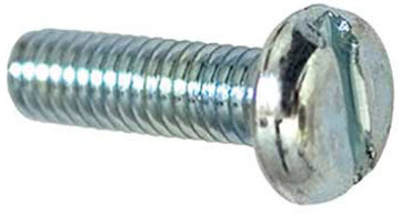
Flathead countersunk screws are preferable for mounting the Alisse adapter to the backbox. Lutron does not provide screws, as the screw size/thread pitch are not standardized across backbox manufacturers. Screws are provided by the backbox manufacturer.
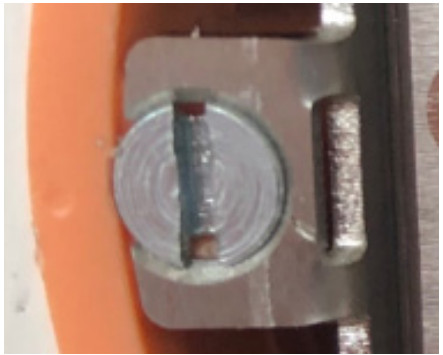
The low profile of the flat countersunk screw head won’t interfere with the keypad assembly.If your backbox is supplied with Panhead screws you will need to drive the screw so that the head does not protrude past the edge of the box.
Flathead countersunk – Preferred screw head type
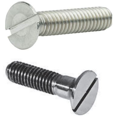
Panhead – Not preferred. If your backbox was supplied with Panhead screws see the following section for Best Practices with Panhead Screws.
Best Practices with Panhead Screws
For 1C and 2C unitsDrive the Panhead screw in as far as possible while keeping the adapter arms flat against the wall surface. Do not overtighten such that adapter arms raise off the surface of the wall.
CORRECTAdapter flat against the wall.
NOT CORRECTScrew over-driven.Adapter raised off of the wall.
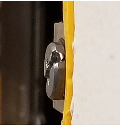
For 3C unitsFor 3C units, Panhead screws should be driven in such that the top of the screw heads is flush with the lip of the backbox.
CORRECTPanhead screw flush with backbox.
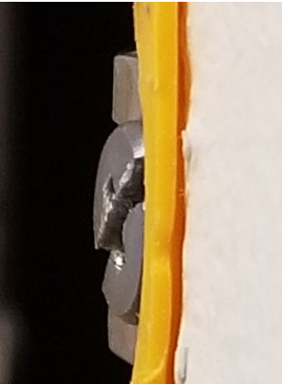
NOT CORRECTPanhead screw protrudes past backbox, not flush with backbox.
Manufacturer’s Backboxes (tested by Lutron)
Compatible Boxes
| Make | Model | Mounting Style | Depth (mm) | Base Unit Fit | Compatibility |
| Simet | PV6OK | Flags and Flanges | 39. | Good | Good |
| Kaiser (Lutron) | 9064-01 (EBB-1-RD) | Flags and Flanges | 62 | Good | Good |
| F-Tronics | E135 | Flags and Flanges | 35 | Good | Good |
| Legrand | 0800-51 | Claws and Flanges | 50 | Good | Good* |
| Legrand | 0800-41 | Claws and Flanges | 40 | Good | Good* |
| Legrand | 080108/080109 | Masonry/No Flange | 40 | Good | Good* |
| Legrand | 0801-01 | Claws and Flange | 40 | Fits, but tight | Good* |
| Legrand | 0801-21 | Claws and Flange | 50 | Fits, but tight | Good* |
Not Recommended Boxes
| Make | Model | Mounting Style | Depth (mm) | Base Unit Fit | Compatibility |
| Debflex | 718300 | Masonry/No Flange | 40 | Good | Ok |
| Debflex | 718361 | Claws and Flanges | 40 | Fits, but Tight | Ok |
| ELKO | E135 | Claws and Flanges | 54 | Good | Ok |
| Vimar | V71701 | Flags and Flange | 50 | Good | Poor |
Non-Compatible Boxes
| Make | Model | Mounting Style | Depth (mm) | Base Unit Fit | Compatibility |
| Legrand | 080021 H | Claws and Flanges | 40 | Will not fit | No |
| Debflex | 718361 | Claws and Flanges | 40 | Will not fit | No |
| ELKO | E135 | Claws and Flanges | 48 | Will not fit | No |
* See previous section Best Practices with Panhead Screws for use of backboxes supplied with Panhead screws.
Lutron and Alisse are trademarks or registered trademarks of Lutron Electronics Co., Inc. in the US and/or other countries.All other product names, logos, and brands are the property of their respective owners.
Lutron Contact NumbersWORLD HEADQUARTERSUSALutron Electronics Co., Inc.7200 Suter RoadCoopersburg, PA 18036-1299TEL: +1.610.282.3800FAX: +1.610.282.1243[email protected]www.lutron.com/supportNorth & South AmericaCustomer AssistanceUSA, Canada, Caribbean: 1.844.LUTRON1 (1.844.588.7661)Mexico: +1.888.235.2910Central/South America: +1.610.282.6701
UK AND EUROPE:Lutron EA Limited125 Finsbury Pavement4th floor, London EC2A 1NQUnited KingdomTEL: +44.(0)20.7702.0657FAX: +44.(0)20.7480.6899FREEPHONE (UK): 0800.282.107Technical Support: +44.(0)20.7680.4481[email protected]
ASIA:Lutron GL Ltd.390 Havelock Road#07-04 King’s CentreSingapore 169662TEL: +65.6220.4666FAX: +65.6220.4333Technical Support: 800.120.4491[email protected]Asia Technical HotlinesNorthern China: 10.800.712.1536Southern China: 10.800.120.1536Hong Kong: 800.901.849Indonesia: 001.803.011.3994Japan: +81.3.5575.8411Macau: 0800.401Taiwan: 00.801.137.737Thailand: 001.800.120.665853Other Countries: +65.6220.4666
Lutron Electronics Co., Inc.7200 Suter RoadCoopersburg, PA 18036-1299 U.S.A.07/2021 P/N 048791 Rev. A
Application Note #791
Customer Assistance — 1.844.LUTRON1
References
[xyz-ips snippet=”download-snippet”]