
![]()
PowPak | InstallationControl Module with DALIPart of the Vive Family220 – 240 V~ 50 / 60 Hz 50 mA
 041797Rev. A02/2021
RMNS-DAL4-SZRMNS-DAL32-SZ
DALI Control: 18 V=Guaranteed Supply Current:
- 8 mA on 4-driver controller (RMNS-DAL4-SZ)
- 64 mA on 32-driver controller (RMNS-DAL32-SZ)Maximum Supply Current: 250 mAImportant Notes: Please read before installing.For installation by a qualified electrician in accordance with all local and national electrical codes.
- Use copper conductors only.
- Check to see that the device type and rating are suitable for the application.
- DO NOT install if the product has any visible damage.
- If moisture or condensation is evident, allow the product to dry completely before installation.
- Operate between 0 °C and 40 °C ambient.
- 0% to 90% humidity, non-condensing.
- For indoor use only.
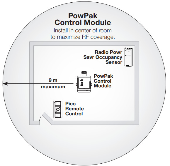
All Wireless Transmitters must be installed within 9 m of the PowPak Control Module with DALI.

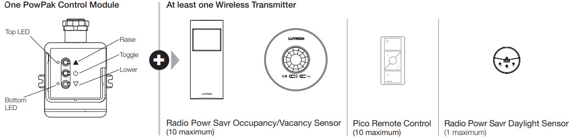
Required ComponentsFor each system, ensure that you have:
Customer Assistance www.lutron.com/support
At least one DALI LED Driver or Fluorescent BallastConsult third-party DALI fixtures installation guide for fixture-specific wiring. This device can be installed on a fixture/troffer, junction box, or marshaling box using the conduit nut or with mounting screws. The device must NOT be mounted inside a fixture/troffer or other metallic enclosure. Improper installation can result in degraded wireless communication, intermittent or sustained communication failures, and will not be covered under warranty. For mounting and wiring, best practices see Lutron Application Note #620 (P/N 048620).

8 mA / 64 mA (based on model) guaranteed for the control lines.May be pre-installed in light fixture.
Start Here
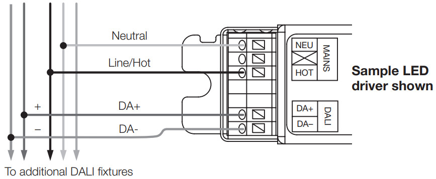
- Mount, Wire, and Install DALI Devices and Lighting FixturesConsult the third-party device installation guide
 WARNING! Shock Hazard. May result in serious injury or death. Turn off power at the circuit breaker before installing the unit.
A Connect mains wiring (hot, neutral) to each fixture.B Connect DALI control to each fixture.
WARNING! Shock Hazard. May result in serious injury or death. Turn off power at the circuit breaker before installing the unit.
A Connect mains wiring (hot, neutral) to each fixture.B Connect DALI control to each fixture. -
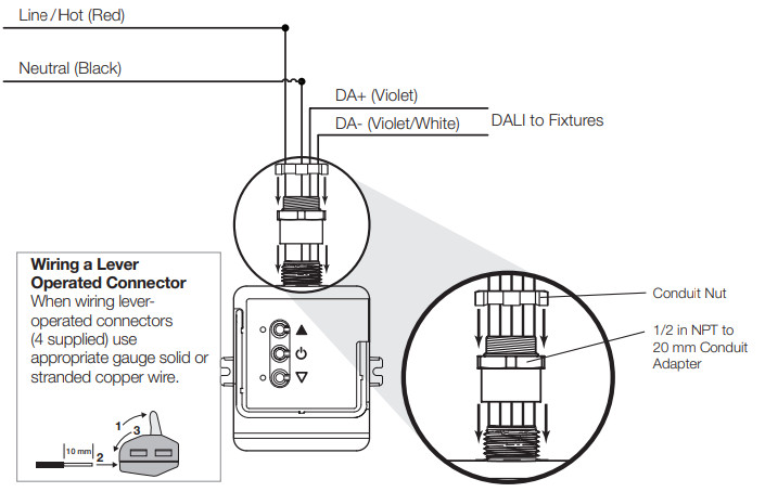
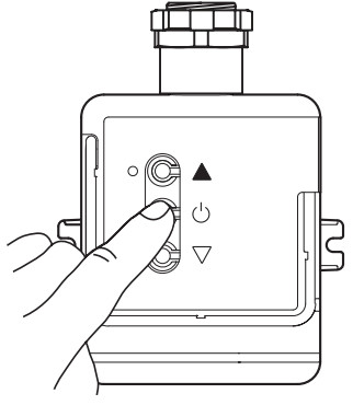
Install PowPak Control Module with DALISuggested Installation Location: Center of room to ensure proper RF coverage of the area.A Install the 1/2 in NPT to 20 mm conduit adapter (provided) onto the PowPak Control Module.B The PowPak Control Module can be installed on a fixture/troffer, junction box, or marshaling box using the conduit nut (provided) or with mounting screws (not provided). Please consult local and national electric codes for proper installation.C Once installed, energize the PowPak Control Module.D Use the Toggle “ ”, Raise “▲” and Lower “ Δ ” buttons to verify control wiring.
Wire Gauge Total DALI-compliant Bus Wire Length 1.5 mm2 (14 AWG) 300 m 0.75 mm2 (18 AWG) 150 m 0.50 mm2 (20 AWG) 100 m -
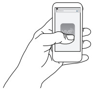
Programming with a Vive Hub
A Use an iOS or Android compatible device. B Download the Lutron Vive app. C Open the app and follow the instructions. Note: For further information on set up, programming, and troubleshooting with a Vive system, please refer to the installation instructions included with the Vive hub or visit www.lutron.com/vive-europeNote: For programming, the PowPak Control Module with DALI without a Vive hub see the reverse side.


Troubleshooting
| Ballasts cannot be controlled locally from PowPak Control Module with DALI. |
• Ensure that the breaker(s) to the PowPak Control Module are energized.• Ensure that the DALI control lines are wired to the lighting fixture(s). Reset to factory defaults. |
| Lights do not dim as expected. | • Ensure that DALI control lines are wired properly. |
| Lights do not respond to Wireless Transmitter(s). | • Ensure that the breaker(s) to the PowPak Control Module and drivers/ballasts are energized.• Ensure that Wireless Transmitters are associated to the PowPak Control Module.• Ensure that Wireless Transmitter(s) are within 9 m of the PowPak Control Module.Reset to factory defaults. |
| Lights are unstable at low-end or flash/flicker at turn-on or turn-off. | • Adjust the low-end trim. |
| Lights are unstable at low-end or flash/flicker at turn-on or turn-off. |
• Ensure that Wireless Transmitter(s) are within 9 m of the PowPak Control Module.• The maximum number of Wireless Transmitters have been associated to the PowPak Control Module. To remove a previously set up Wireless Transmitter, tap a Wireless Transmitter button three times; on the third tap-hold for three seconds and then tap three more times. |
Start Here
- Associate Wireless Transmitters toPowPak Control Module with DALI Before beginning this step, make sure that there are no other PowPak modules being set up within the same building. It is possible that wireless transmitters from othersystems can be incorrectly associated with this module.A On the PowPak Control Module, hold the Toggle button “ ” for 6 seconds until lights flash.Both LEDs will begin flashing twice per second. B Hold the indicated button on each transmitter for 6 seconds. Lights will flash to show that wireless transmitters have been associated. LEDs also flash upon successful association. C On the PowPak Control Module, hold the Toggle button “ ” for 6 seconds to save association. Lights will return to high-end and LEDs will stop flashing.D Permanently install wireless transmitters (consult individual component installation guides for information).Reset Factory DefaultsNote: In some instances, it may be necessary to reset the PowPak Control Module with DALI and connected devices back to factory default settings. Before beginning, make sure that all devices are connected and powered.A Triple-tap the Toggle button “ ” on the PowPak Control Module and hold until both LEDs begin to flash slowly; release button.B Within 3 seconds of the start of flashing, triple-tap the same button again and the LEDs will flash rapidly indicating that the unit has been reset to factory defaults.Note: Any associations or programming previously set up with the PowPak will be erased and will need to be re-programmed.
-
Calibrate the Radio Power Savr Daylight SensorDaylight Sensor will control all wired fixtures equally.A Press and release the “Cal.” button on the Daylight Sensor.B Set lights in the room to desired light level.C Press and hold the “Cal.” button for 6 seconds.D Exit room for 5 minutes to complete calibration.Note: When calibration has completed, all lights will flash and begin to respond to daylight.Multiple Daylight Rows (Optional)For every row of daylighting a separate PowPak Control Module must be used. For a detailed setup refer to the tuning section of the Radio Power Savr Daylight Sensor installation guide.• Select the PowPak Control Module that you want to adjust by pressing the Toggle button.
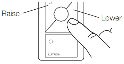
- Set a Favorite Light Level (Optional)For Pico remote controls with a Favorite Button.A Adjust lights to the desired level:Use the Raise button “ ” or Lower button “ ” on the Pico remote control.B Save favorite level:Press and hold the Favorite button for 6 seconds. The load will flash 3 times to confirm that the Favorite level is saved.
- Set Low-End Trim and High-End Trim (Optional)For best results, minimize the amount of sunlight entering the room before performing the following procedures.NotesDepending on the fixture manufacturer or load, low-end trim and high-end trim may need to be adjusted.• Trim low-end to ensure a stable light level because some loads will flicker or drop out if trimmed too low.• Be sure that you can turn on the lights to the low-end trim level without any abnormal operation.• The factory default high-end trim is suitable for most applications but can be adjusted as desired.Low-End TrimA Enter low-end trim adjustment mode: Press and hold the Lower button “ Δ ” on the fixture control for 12 seconds.The lights will flash and the bottom LED will begin flashing.B Adjust the low-end trim:Use the Raise button “▲” and Lower button “ Δ ” on the PowPak Control Module to adjust and set the lights to the desired low-end (0.1 to 45%).Note: Low-end depends on the minimum output of connected drivers or ballasts.C Save the low-end trim:Press and hold the Toggle button “ ” for 6 seconds to save the setting.The bottom LED will begin flashing and then turn solid to indicate a new level has been saved.High-End TrimA Enter high-end trim adjustment mode:Press and hold the Raise button “▲” on the fixture control for 12 seconds.The lights will flash and the top LED will begin flashing.B Adjust the high-end trim:Use the Raise button “▲” and Lower button “ Δ ” on the PowPak Control Module to adjust and set the lights to the desired high-end (55 to 100%).C Save the high-end trim:Press and hold the Toggle button “ ” for 6 seconds to save the setting.The load status LED will begin flashing and then turn solid to indicate a new level has been saved.Customer Assistance www.lutron.com/support
- Set Minimum Light Level (Optional)Certain applications (e.g., hallways), may require that the lights never turn off. For these areas, activate Minimum Light Level mode.A Enter minimum light level adjustment mode:Press and hold the Goggle button “ u” and the Lower button “ Δ ” for 12 seconds. Lights will flash high-low-high and both LEDs will begin flashing.If lights stop flashing and turn off, the minimum light level is set to OFF (default).If lights stop flashing and go to low-end, the minimum light level is ON and set to low-end.B Change the minimum light level:Press the Raise button “▲” to set the minimum light level to low-end.Press the Lower button “ Δ ” to set the minimum light level to OFF.C Save the minimum light level:Press and hold Goggle button “ ” for 6 seconds. Both LEDs will quickly flash to indicate that the new level has been saved.
- Set Occupancy Light Levels (Optional)Note: Unoccupied light level is always the minimum light level and cannot be adjusted.A Set desired occupancy light levels:Use the Raise/Lower buttons “▲ / Δ ” on the PowPak Control Modules or the Raise/Lower buttons “ ” on associated Pico Remote Controls to adjust lights to the desired level.Note: Setting lights to OFF during this step will make that control module unaffected by occupancy (will function as vacancy only).B Save occupancy light levels:Press and hold the Test button for 6 seconds on any associated Radio Powr Savr Occupancy Sensor without a Lights On button. Release when the Sensor lens starts to flash.
 B Hold the indicated button on each transmitter for 6 seconds. Lights will flash to show that wireless transmitters have been associated. LEDs also flash upon successful association.
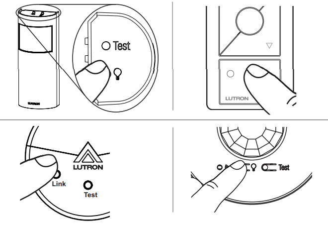 C On the PowPak Control Module, hold the Toggle button “
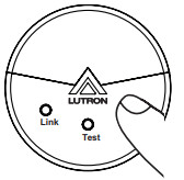
 Use the Raise button “
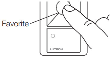 Press and hold the Favorite button for 6 seconds. The load will flash 3 times to confirm that the Favorite level is saved.
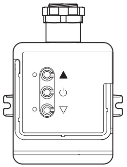 Low-End TrimA Enter low-end trim adjustment mode: Press and hold the Lower button “ Δ ” on the fixture control for 12 seconds.The lights will flash and the bottom LED will begin flashing.B Adjust the low-end trim:Use the Raise button “▲” and Lower button “ Δ ” on the PowPak Control Module to adjust and set the lights to the desired low-end (0.1 to 45%).Note: Low-end depends on the minimum output of connected drivers or ballasts.C Save the low-end trim:Press and hold the Toggle button “
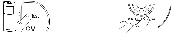
Customer Assistance:
India: +91.124.439.0130Other Countries: +1.610.282.3800www.lutron.com/supportLimited Warranty: Hereby, Lutron Electronics Co., Inc. declares that the radio equipment type RMNS-DAL32-SZ and RMNS-DAL4-SZ is incompliance with Directive 2014/53/EU.The full text of the EU declaration of conformity is available at the following internet address: www.lutron.com/cedoc
Lutron, Pico, and PowPak are trademarks of Lutron Electronics Co., Inc., registered in the U.S. and other countries. Radio Powr Savr and Vive are trademarks of Lutron Electronics Co., Inc.App Store is a trademark of Apple Inc., registered in the U.S. and other countries. iOS is a registered trademark of Cisco in the U.S. and other countries and is used under license. Android, Google Play and the Google Play logo are trademarks of Google Inc. DALI is a trademark of ZVEI. ©2021 Lutron Electronics Co., Inc.
References
[xyz-ips snippet=”download-snippet”]