LUTRON P-PKG1WB-WH Caseta Wireless Smart Home Dimmer Switch and Pico Remote Kit
In-wall switchWelcome— and thank you for purchasing a Caséta Wireless in-wall switch. In order to control your lights from an app or remote, you’ll need to replace an existing switch with a Caséta Wireless in-wall switch.We hope you enjoy the convenience of Caséta Wireless!
Double your warranty
Love Caséta Wireless products? Have ideas for making them better? Tell us what you think and we’ll extend your warranty by 1 year.www.casetawireless.com/register
![]()
Contents supplied
|
|
|
|
|
|
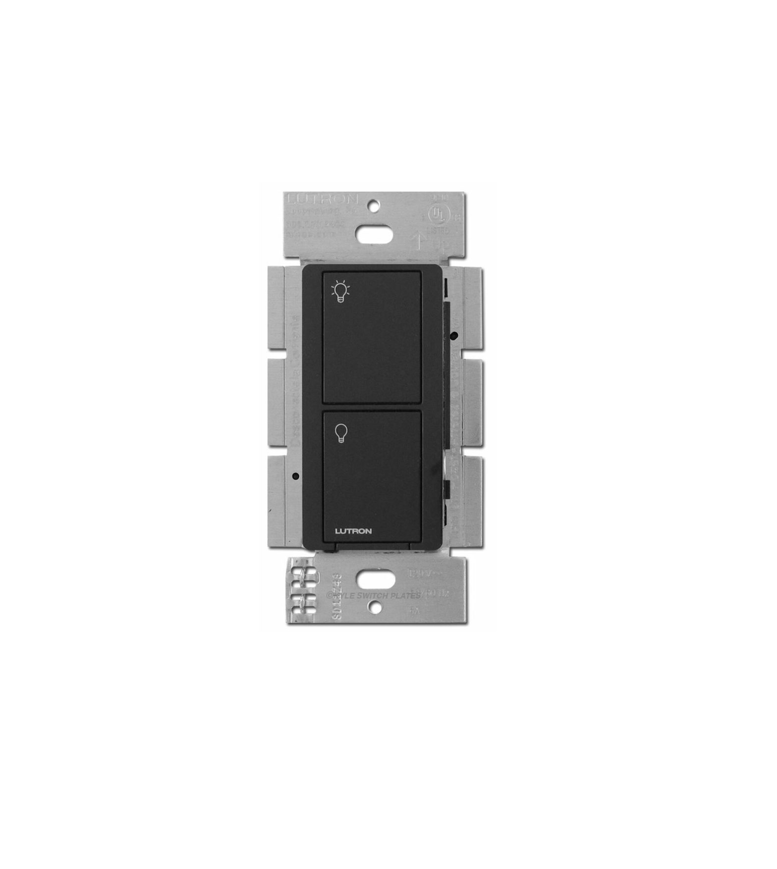
 In-wall switch (PD-5WS-DV)
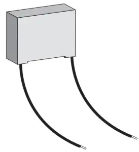 LUT-MLC* load adapter
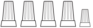 Wire connectors (5)
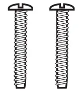 Screws (2)
Tools you’ll need
|
Flat-head screwdriver |
Phillips-head screwdriver |
|
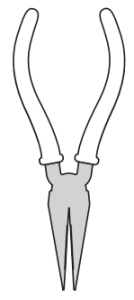 Pliers
* Note: A LUT-MLC may be required to ensure proper function with CFL, LED, ELV, and fluorescent lighting. Please see instructions for installing the LUT-MLC that can be found on page 2 of this install guide. The instructions can also be found by visiting www.casetawireless.com/lutmlc
Installing your switch
Installation for lights with one wall switch (single-pole)
Turn power off at circuit breaker!
 |
WARNING: SHOCK HAZARDMay result in serious injury or death. Turn off power at circuit breaker or fuse before installing. |
| Important note:Some lights have one wall switch, while others have two or more wall switches (such as stair lights, which have a switch at both the top and bottom of the stairs). We’ve included instructions for lights with one wall switch (called a single pole). If your light has more than one switch (called a 3-way), please visit www.casetawireless.com/3way for complete installation instructions and how-to videos. |
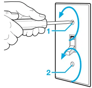
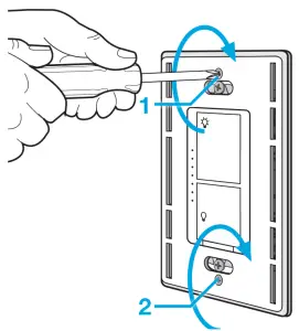
Remove existing switch from wall
- Remove the wallplate from switch.

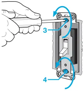
- Remove the switch and pull it away from the wall.
- Disconnect all three wires* from the switch.
* If your switch has more than 3 wires attached, see “Installing Caséta Wireless in a 3-way switch application” video at www.casetawireless.com/3way
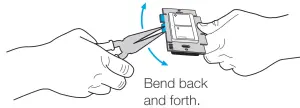
Remove side sections (if necessary)
Do not remove outside side sections on switches at the end of gang.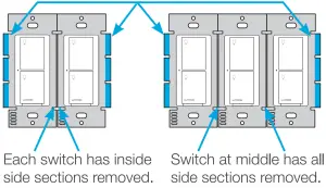
|
Important note:Removing side sections reduces the switch’s maximum wattage rating. See the chart below for maximum load information.
|
1 The in-wall switch is ULR Listed for use with all magnetic and electronic fluorescent ballasts.2 The maximum lamp wattage is determined by the efficiency of the transformer, with 70%–85% as typical. For actual transformer efficiency, contact either the fixture or transformer manufacturer.The total VA rating of the transformer(s) shall not exceed the VA rating of the in-wall switch.
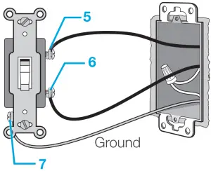
Connect the switch
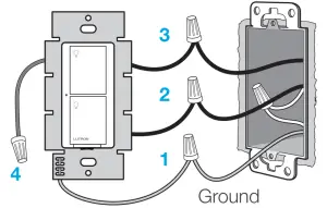
- Connect the bare copper (or green) “ground” wire from the wallbox to the green wire on the switch using a wire connector.
- Connect either of the remaining wires from the wallbox to either of the black wires on the switch using a second wire connector.
- Connect the remaining wire from the wall to the other black wire on the switch using a third wire connector.
- Cap off the blue wire on the switch using the small wire connector. *
* Note: The blue wire is only used in 3-way installations. See www.casetawireless.com/3way for more information.* Note: A LUT-MLC may be required to ensure proper function with CFL, LED, ELV, and fluorescent lighting.Please see instructions for installing the LUT-MLC that can be found on page 2 of this install guide.The instructions can also be found by visitingwww.casetawireless.com/lutmlc
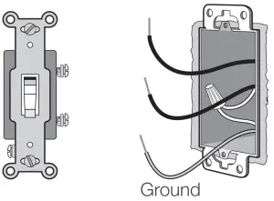
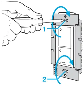
Mount the switch
Use the screws provided.
Attach the wallplate
Attach the adapter to the switch using the screws provided and snap on the wallplate.
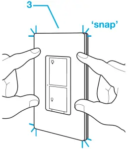
(If you installed the switch next to other switches or dimmers, you’ll need to install a wallplate with the correct size / number of openings to accommodate all the devices.)
Turn power on at circuit breaker
CAUTIONUse only with permanently installed lighting loads or with general purpose fan loads.
CodesInstall in accordance with all national and local electrical codes.
GroundingWhen no “grounding means” exist in wallbox, the National Electrical Code (NEC®) allows a control to be installed as a replacement if 1) a nonmetallic, noncombustible faceplate is used with nonmetallic attachment screws or 2) the circuit is protected by a ground fault circuit interrupter (GFCI). When installing a control according to these methods, cap or remove green wire before screwing control into wallbox.
FCC / IC InformationThis device complies with part 15 of the FCC Rules and Industry Canada license-exempt RSS standard(s). Operation is subject to the following two conditions: (1) This device may not cause interference, and (2) this device must accept any interference, including interference that may cause undesired operation. Modifications not expressly approved by Lutron Electronics Co., Inc. could void the user’s authority to operate this equipment.Note: This equipment has been tested and found to comply with the limits fora Class B digital device, pursuant to part 15 of the FCC Rules. These limits are designed to provide reasonable protection against harmful interference in a residential installation. This equipment generates, uses and can radiate radio frequency energy and, if not installed and used in accordance with the instructions, may cause harmful interference to radio communications.However, there is no guarantee that interference will not occur in a particular installation. If this equipment does cause harmful interference to radio or television reception, which can be determined by turning the equipment off and on, the user is encouraged to try to correct the interference by one or more of the following measures:—Reorient or relocate the receiving antenna.—Increase the separation between the equipment and receiver.— Connect the equipment into an outlet on a circuit different from that to which the receiver is connected.—Consult the dealer or an experienced radio/TV technician for help
Supported Loads (120 V~
 |
LED— up to 5 A |
 |
CFL— up to 5 A |
 |
Incandescent / Halogen— up to 600 W |
 |
MLV— up to 600 VA / 475 W |
|
ELV— up to 600 W |
 |
Fluorescent— up to 5 A |
 |
General Purpose Fan— up to 3 A |
Supported Loads (277 V~)
|
LED— up to 5 A |
|
CFL— up to 5 A |
|
Incandescent / Halogen— up to 1350 W |
|
MLV— up to 1350 VA / 1075 W |
|
ELV— up to 1350 W |
|
Fluorescent— up to 5 A |
Lutron Electronics Co., Inc.7200 Suter RoadCoopersburg, PA 18036-1299, U.S.A.
Using your Caséta Wireless kit
(sold separately)
With a smartphone or tablet (Smart Bridge required, sold separately)
The Caséta Wireless switch can be controlled from a smartphone when used with the Lutron Smart Bridge.If you are using the switch and remote control with the Lutron Smart Bridge follow the instructions below.
| Note: If you are using the switch and remote control with another manufacturer’s bridge, please refer to that manufacturer’s instructions for set-up. |
Download the Lutron® app


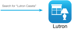
www.casetawireless.com/LutronApp
Apple is a trademark of Apple Inc., registered in the U.S. and other countries. App Store is a service mark of Apple Inc.
Launch the Lutron® app
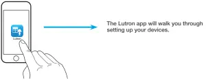
Use the Lutron app to complete ALL remaining steps
 |
Add devices
|
 |
Control three ways |
 |
Schedule your lights |
 |
Connect while away |
Without a smartphone or tablet(Smart Bridge not required)
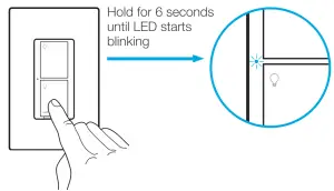
Pairing the switch and Pico remote control
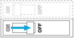
- Press and hold “off” button on the switch
- Press and hold “off” button on remoteRepeat steps to pair other Pico remote controls.
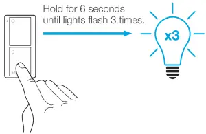 Repeat steps to pair other Pico remote controls.
Using your controls
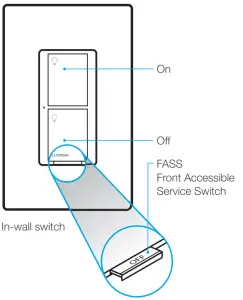
Replacing light bulbs using FASS
Pull the FASS out on the in-wall switch to remove power at the light socket.
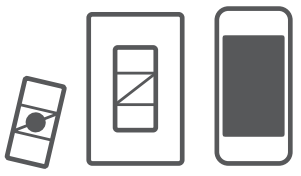
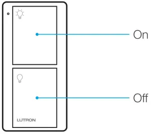 Pico remote control (sold separately)
Important notes:
|
For advanced features, tips for using Caséta Wireless products with CFLs and LEDs, the complete Caséta Wireless product line, and more, please visit www.casetawireless.com/features
Troubleshooting
| Symptoms | Probable cause and action |
| Light does not turn on or in-wall switch LED does not light up. |
|
| Light does not respond to Pico remote control. |
|
|
Proper bulb operation requires a LUT-MLC (included in the package with the switch). Please visit www.casetawireless.com/lutmlc for installation instructions. |
Go to www.casetawireless.com/support for additional troubleshooting suggestions.
Device RatingsIn-wall switchPD-5WS-DV120 / 277 V~ 50/60 Hz
Installing the LUT-MLC in a load fixture or junction box
- Connect one lead of the LUT-MLC to the neutral (white) wire.
- Connect the other lead of the LUT-MLC to the switched hot (black) wire.
Junction Box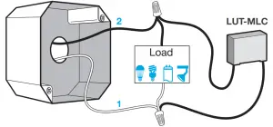
| WarrantyFor warranty information, please visit www.casetawireless.com/warranty |

References
[xyz-ips snippet=”download-snippet”]