QS DIN Rail PanelsInstallation Instructions Please Read Before Installing

P/N 043557 Rev. B 07/2021
| Model | Voltage/ Frequency | Input Maximum | Feed | Breaker Capacity |
| PD8-65A-120L3-15PD8-65B-120L3-15 | 120/240 V– 50/60 Hz | 125 A | 1 Phase,3 Phase | 15 A |
| PD8-65A-120L3-20PD8-658-120L3-20 | 20 A | |||
| P08-65A-120L4-15PD8-658-120L4-15 | 120/208 V– 50/60 Hz | 3 Phase, 4-Wire | 15 A | |
| PD8-65A-120L4-20PD8-658-120L4-20 | ||||
| PD8-B-ASM | 120/240 V– 50/60 Hz | 125 A | 1 Phase, 3-Wire | 15 A |
| 120/208 V– 50/60 Hz | 3 Phase, 4-Wire | 20 A | ||
| PD2-16T-DV PD4-42T-DV PD6-42T-DV PD8-65T-DV PD10-65T-DV | 120 V– 50/60 Hz | 20 A max. input feed (multiple feeds may be present) | N/A | N/A |
| PD2-S-ASM PD4-C-ASM PD6-S-ASM PD8-C-ASM PD1O-S-ASM | 120/277 V– 50/60 Hz | 20 A max. input feed (multiple feeds may be present) | N/A | N/A |
Important Notes
Codes:
- All wiring must be installed in accordance with all local and national electrical codes.
- Breaker panels are required to be installed to provide sufficient access and working space according to the National Electric Code (NEC®). A typical installation may require 3 ft to ft (0.914 m to 1.22 m) in front of the panel and 30 in (772 mm) width to provide sufficient space for panel access.
- Typical code requirements may include Maximum and minimum breaker height above the floor, proximity to the distribution panel, room size, and room entrance specifications. Check local code for proper installation.
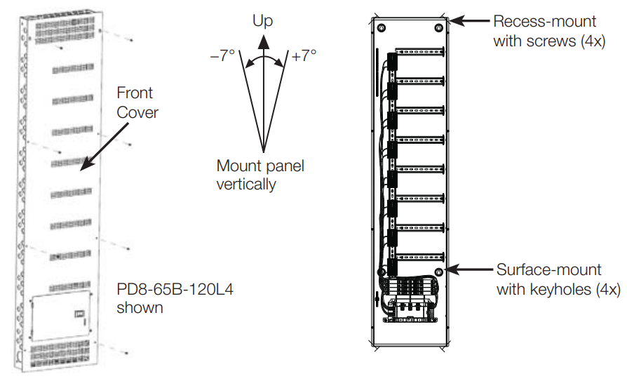
Cooling: This equipment is air-cooled. Mount in a place where the vented cover will not be blocked. Clearance of 12 in (304 mm) is required above and in front of the unit. Clearance of 6 in (152 mm) is required below the unit to the floor.Environment: This equipment is intended for indoor use only; in a 32 °F to 104 °F(0 °C to 40 °C) setting with relative humidity less than 90%, non-condensing.Mounting Location: DIN-Power Modules (DPMs) will hum slightly and internal relays will click while in use. Mount in a location where such noise is acceptable.The panel must be mounted within +/- 7° of vertical. Mount the panel so that line-voltage wiring will be at least 6 ft (1.8 m) from audio and video equipment or radiofrequency devices equipment and wiring.
Installation
- Turn OFF all power sources to the feed to the panel
- Remove panel front cover
 WARNING; Electric Shock Hazard. May result in Serious Injury or Death. To avoid the risk of electric shock, locate and lock the supply breaker in the OFF position before wiring to the input terminals or terminal blocks.
 - Mount rough-in panel using one of the following methods (mounting hardware is not provided):a. Surface-mount: Use keyholes with bolts sufficient for 110 lb (50 kg) load, 1/4 in (M6) bolts recommend ed.b. Recess-mount: Use screws sufficient for 110 lb (50 kg) through the corners of the panel.Mount panel flush to or not more than 1/8 in (3 mm) below the finished wall surface.
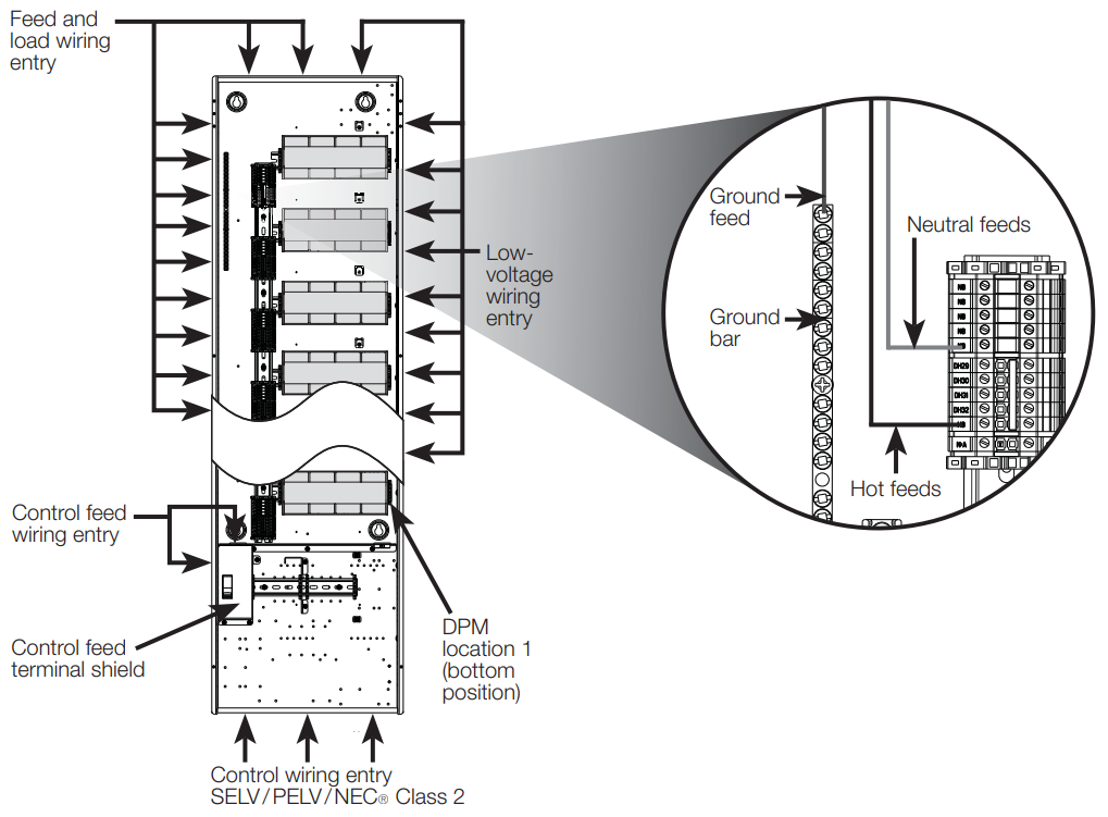
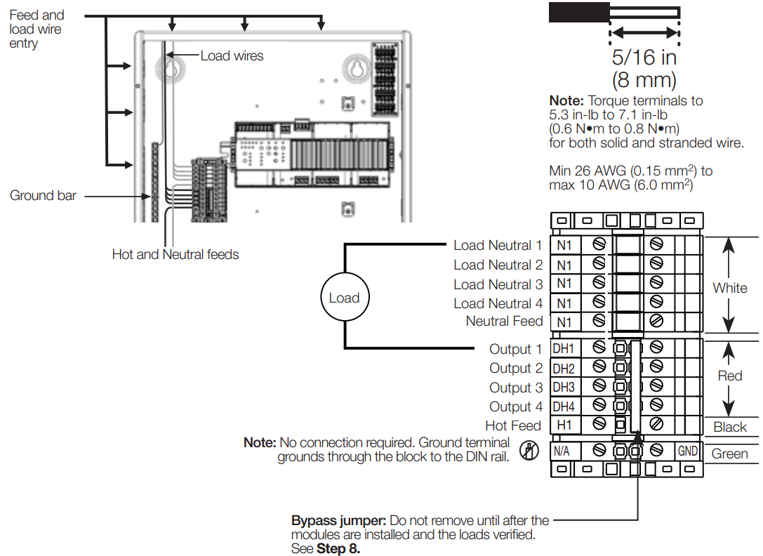
- Run main feed into the panel (breaker panel only)Locations to run the main feed and load wiring into the panel are shown below.DPMs will be to the right side of each row as shown below.Feed sizing:– 120L3 panels: Should be fed with a single-phase, 3-wire feed. Lutron recommends an 80 A breaker if fully loading the power modules. This breaker size doesn’t include capacity for general-purpose breakers.– 120L4 panels: Should be fed with a 3-phase, 4-wire feed. Lutron recommends an 80 A breaker if fully loading the power modules. This breaker size doesn’t include capacity for general-purpose breakers.
| Lug, Wire, and Torque Information | ||
| Lug Type | Wire Range (AWG) | Torque (in-lb/N•m) |
| Main & Neutral Lugs | 6-2/0 Cu/A1 | 50/5.65 |
| Ground Lug | 6-2/0 Cu/A1 | 50/5.65 |
Note: For ease of installation, you may move the small ground bar and attached the ground lug to the alternate location shown in the diagram below. Torque the ground bar mounting screws to 30 in-lb (3.39 N•m). Confirm that modified location meets NECR installation requirements.
Install the supplied yellow covers over the main lugs.

Install breaker and branch circuit wiring on extra breaker slots (optional)
The panel has 4 available positions for running branch circuits to other devices or panels. Use only Square D, QO plug-in mount circuit breakers in these positions.Note: Remove the filler clips in the front cover for each respective breaker added.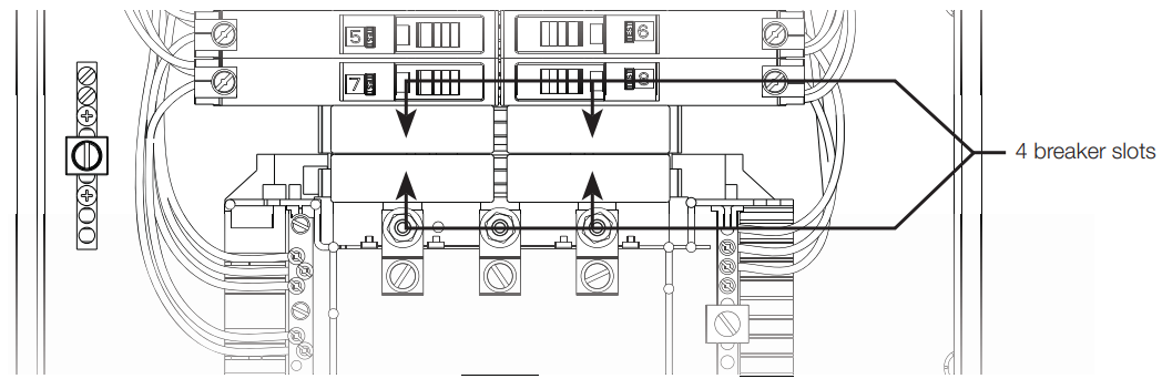
![]() WARNING; Electric Shock Hazard. May Result in Serious Injury or Death.Disconnect all power sources before servicing the unit. For use only with Square D circuit breakers. The use of non-Square D circuit breakers may adversely affect user safety and impair reliability.
WARNING; Electric Shock Hazard. May Result in Serious Injury or Death.Disconnect all power sources before servicing the unit. For use only with Square D circuit breakers. The use of non-Square D circuit breakers may adversely affect user safety and impair reliability.
Run Feed Wiring into Feed-Through Panel
Wire Control Feed (control panels only)
Remove control feed terminal shield and wire as shown below. Lutron recommends a dedicated feed for this purpose. The power supply will draw a maximum of 0.7 A. Leave this switch off until the power supply and low-voltage interface or processor is installed.Note: Hot and neutral terminal blocks for field wiring have a dedicated wire entry point and screw. Do not double-up wires under factory-installed wiring.
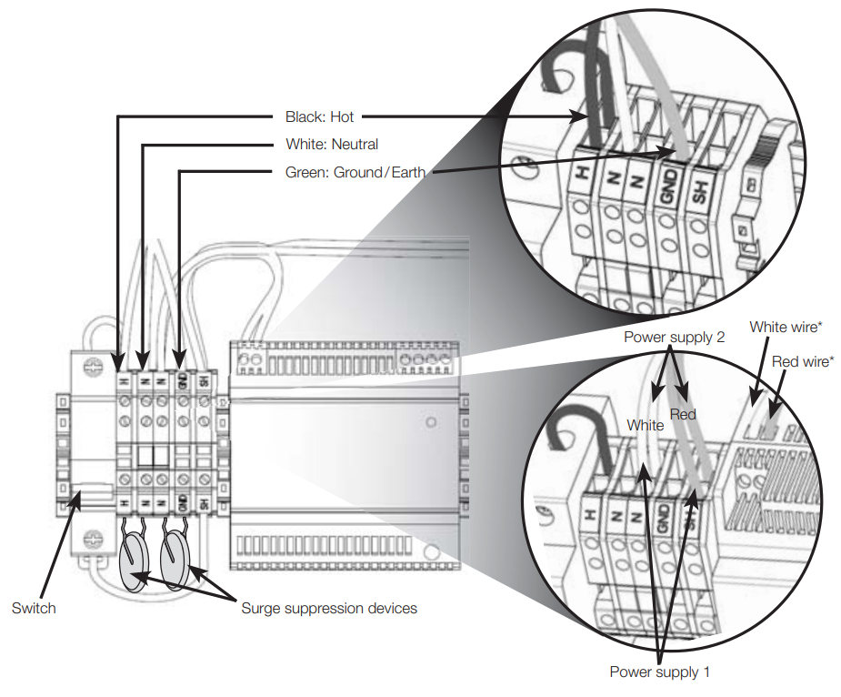
* Note: White neutral wire goes into negative (-) terminal of power supply and red switched hot wire (SH) goes into the positive (+) terminal of the power supply.
For increased system reliability, HomeWorks QS processors can be powered by an uninterruptible power supply (UPS) that incorporates overvoltage protection, brown-out protection, and battery backup. When selecting a UPS, allow 240 VA of capacity for each processor on the UPS. A single large UPS for all processors is better than an individual UPS for each processor. This prevents inconsistent system operation on battery backup if the individual UPS units power down at different times.
Install load wiring
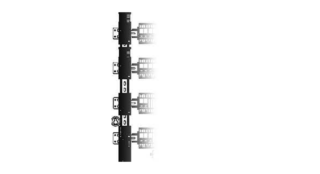
Each module controls up to 4 loads. Label each wire clearly as you connect them to the terminal blocks. This panel comes with terminal blocks and jumpers to allow load wiring prior to DIN power modules being installed. Wiring (shown below) is for *-4A-120-D, *-4A1-D, *-4A5-D, *-4S8-120-D, and *-4T5-120-D using a single feed.Note: Wiring for *-4M-120-D modules will differ. For wiring, refer to the installation instructions provided with the module. Cap off the load wiring with wire connectors rather than terminating it to the terminal blocks.Note: This panel is factory wired for use with a single feed to power *-4T5-120-D modules. Cap 0 –10 V- communication wires until modules arrive. Leave enough wire to make it to the terminals on the module which will be located near the far right side of the DIN row.Note: *-2ECO and *-2DALUNV-D modules will not have any loads landed on the Neutral or DH terminal blocks. Cap EcoSystem and DALI communication wires until modules arrive. Leave enough wire to make it to the terminals on the module which will be located near the far right side of the DIN row.Note: * Indicates LQSE or QSN.
| Branch Neutral and Equipment Ground Bar Information | |||
| Wire Range (AWG) | Torque (in-lb/N•m) | ||
| Bar with 2 screws sizes | Bar with 1 screwsize | ||
| Large Screws | Small Screws | ||
| 1/0-3 Cu/AI | 50/5.65 | – | |
| 4 Cu/AI | 45/5.08 | – | 35/3.95 |
| 6 Cu/AI | 45/5.08 | 25/2.82 | 35/3.95 |
| 8 Cu/AI | 40/4.52 | 10/1/13 | 25/2.82 |
| 10-14 Cu | 35/3.95 | 10/1/13 | 20/2.26 |
| Equipment Ground Combinations and Torque Information | |||
| (2) 14 Cu | 25/2.82 | ||
| (2) 12 Cu | 25/2.82 |
Test all load wiring
The terminal blocks with pre-installed bypass jumpers will distribute power to each load and must not be removed until after all loads are fully tested and modules have been installed. Place the front cover on the panel before testing all load wiring. Turn on input power to each DPM location. Check all connected loads to ensure that they have power. If a circuit breaker trips, a wiring error exists and must be resolved.10. Install DPMs and connect to panel terminalsTurn off power to the panel before installing DPMs.
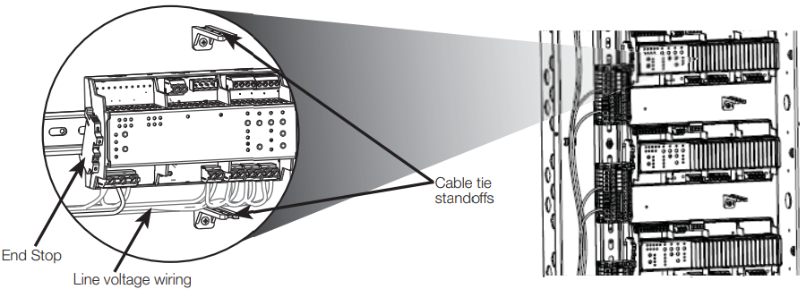
![]() WARNING; Electric Shock Hazard. May Result in Serious Injury or Death.To avoid the risk of electric shock, locate and lock the supply breaker in the OFF position before wiring to the input terminals or terminal blocks.Install modules on the right side of each row. Place an end stop to the left of each module or module and terminal blocks (provided with the panel).Connect the terminal blocks on each respective module to the appropriate panel terminal blocks. See install guide included with each respective module.Dress line voltage wires away from low-voltage (Class 2) wires per local and national codes. This includes low-voltage wires connected to a wire landing board (if installed).
WARNING; Electric Shock Hazard. May Result in Serious Injury or Death.To avoid the risk of electric shock, locate and lock the supply breaker in the OFF position before wiring to the input terminals or terminal blocks.Install modules on the right side of each row. Place an end stop to the left of each module or module and terminal blocks (provided with the panel).Connect the terminal blocks on each respective module to the appropriate panel terminal blocks. See install guide included with each respective module.Dress line voltage wires away from low-voltage (Class 2) wires per local and national codes. This includes low-voltage wires connected to a wire landing board (if installed).
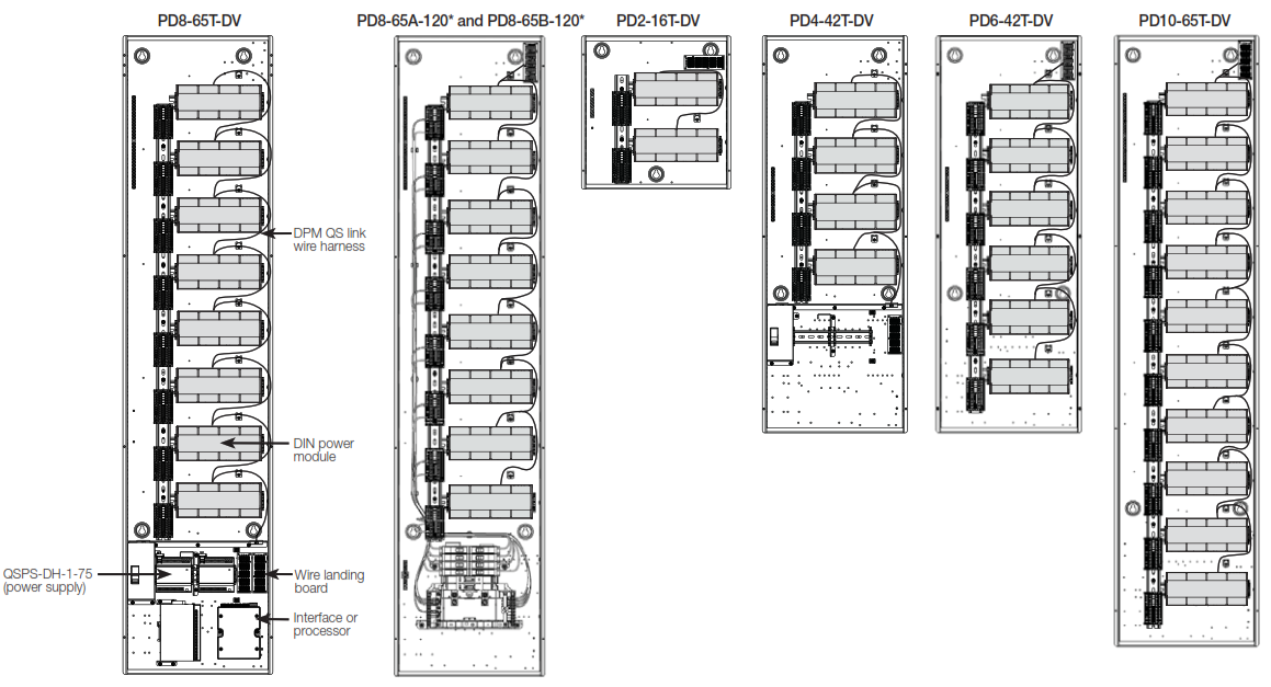
Install QS-WLB and Connect QS Link to modules
– Install the wire landing board (QS-WLB). Use group A position for breaker and satellite panels (group D can be used as an alternate location). Use group B and C positions for control panels.See the image below.– Connect all modules in the panel using the provided QS Link wiring harness and QS wire landing board (QS-WLB). Using provided cable ties, cable tie harness wiring to cable tie standoffs and to the side of the enclosure.See the image below.– NOTE: Dress line voltage wires away from low voltage (Class 2) wires per local and national codes.

Check that all bypass jumpers are installed
Bypass jumpers distribute power to each load and should not be removed until after all modules and loads are installed and verified.13. Turn on the power and check for errorsTurn on power to the main feed and then individual circuit breakers. If any circuit breakers trip, an error needs to be resolved.Note: LQSE-4A-120-D, LQSE-4A5-120-D, QSN-4A5-D, and LQSE-4A1-D will show error blink codes when bypass jumpers are still installed. This is okay. The error codes will clear in Step 14.
Turn off the power and remove bypass jumpers
![]() WARNING; Electric Shock Hazard. May Result in Serious Injury or Death.To avoid the risk of electric shock, locate and lock the supply breaker in the OFF position before wiring to the input terminals or terminal blocks.After all wiring issues are resolved, turn off the main power feed to the panel and remove the bypass jumpers from H and DH terminals. Store the bypass jumper for possible later use.Note: Bypass jumpers should be installed any time a breaker is turned off for work on a load. The bypass jumpers reduce the chance of module damage due to short circuits or miswire during work. This damage IS NOT COVERED by the product warranty.
WARNING; Electric Shock Hazard. May Result in Serious Injury or Death.To avoid the risk of electric shock, locate and lock the supply breaker in the OFF position before wiring to the input terminals or terminal blocks.After all wiring issues are resolved, turn off the main power feed to the panel and remove the bypass jumpers from H and DH terminals. Store the bypass jumper for possible later use.Note: Bypass jumpers should be installed any time a breaker is turned off for work on a load. The bypass jumpers reduce the chance of module damage due to short circuits or miswire during work. This damage IS NOT COVERED by the product warranty.
Restore power to the panel
Restore the power to the panel and each branch circuit.16. Install coverTighten the cover screws to 17 in-lb (1.9 N•m).17. Leave this instruction sheet in a safe, accessible location
The following images show low-voltage interfaces and processors placement location options.Use the installation guides provided with the devices being installed. Those guides include all the installation and setup information needed. Note each processor and PoE switch requires its own power supply.
Two Power Supplies and Two PoE Switches

Two Power Supplies and Two DIN Mounted Processors
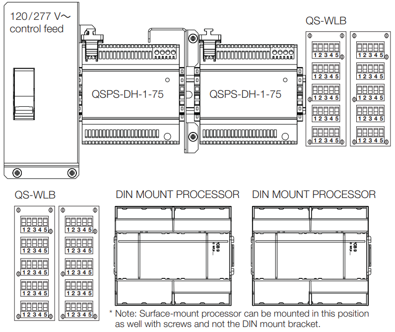 Two Power Supplies and One PoE Switch and DIN Mounted Processor
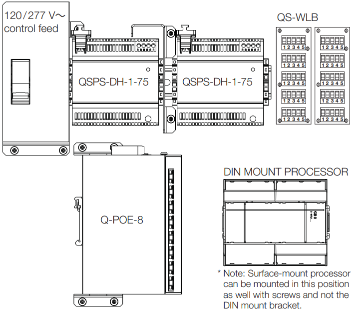
Two Low-Voltage Interfaces

The following information shows what devices and how many can be installed inside a panel.NOTE: Wireless devices cannot be installed inside the enclosure due to the RF nature of the devices.
| Maximum devices | ||||
| Model | DPM | Interface or processor or PoE Switch | WLB | OSPS-DH-1 -75 |
| PD2-161.DV. PD2-S.ASM | 2 | 0 | 1 | 0 |
| PD4.42TDV. PD4-0ASM | 4 | 2 | 4 | 2 |
| F1:6-427DV, PD6-S.A.SM | 6 | 0 | 1 | 0 |
| PC6.65TDV P08-CASM | 8 | 2 | 4 | 2 |
| PD10-65T-OV. F010-S-ASM | 10 | 0 | 1 | 0 |
| HomeWorks | Description |
| LOSE-415-120-D | 120 V-,– 0-10 V— Module |
| LOSE-4S8-120-D | 120 V— Switching Module |
| LOSE-2DALUNV-120-D | 120/240 V-.– DALI Universal Module |
| LOSE-2ECO-D | 120 V— Ecosystem Module |
| LOSE-4A1-D | 120 V— 1 A Phase Adaptive Module |
| LOSE-4A-120-D | 120 V— Phase Adaptive Module |
| LOSE-4M-120-D | 120 V— AC Motor Controller |
| LOSE-4A5-120-D | 120 V— PRO LED+ Phase Adaptive Module |
| Athena | Description |
| OSN-4A5-D | 120/277 V— PRO LED+ Phase Adaptive Module |
| OSN-415-120-D | 120 V– 0-10 V— Module |
| OSN-4S8-120-D | 120 V– Switching Module |
| OSN-2DALUNV-D | 120 V– DALI Universal Module |
| OSN-2ECO-120-D | 120 V— EcoSystem Module |
NOTE: See individual product specifications for more details.NOTE: Lutron recommends placing dimming modules (e.g., LQSE-4A-120-D and LQSE-4A1-D) higher in the panel.Wire Landing Board (WLB)
| QS-WLB | QS link jumper board |
| Maximum devices | ||||
| Model | DPM | Interface or processor or PoE Switch | WLB | USPS-DH-1-75 |
| PD8-65A-120L3-15PD8 65B-12013-15 | 8 | 0 | 1 | 0 |
| P08-65A-120L3-20P08 65B-12013-20 | 8 | 0 | 1 | 0 |
| P08-65A-120L4-15P08 65B-12014-15 | 8 | 0 | 1 | 0 |
| PD8-65A-120L4-20PD8 65B-12014-20 | a | 0 | 1 | 0 |
| PD8-B-ASM | 8 | 0 | 1 | 0 |
Low-Voltage Interface / Processor and Power Supply
| HomeWorks | Description |
| HOP7-1 or HQP7-2 | HomeWorks QSX 1 or 2 Link Processor |
| HOP7-MDU-1 or HOP7-MDU | MDU 1 or 2 Unk Processor |
| OSPS-DH-1-75 | 24 V— 75 PDU Power Supply |
| CLE-I0 | Contact Closure Interlace |
| QSE-CI-DMX | DMX Interface |
| Athena | Description |
| QP-1L or QP-2L | Athena 1 or 2 Unk Processor |
| 0-POE-8 | 8-Port PoE Switch |
| CAPS-DH-1-75 | 24 V— 75 PDU Power Supply |
| OSE-I0 | Contact Closure Interface |
| OSE-CI-DMX | DMX Interface |
| OSE-CI-NWK-E | Network Interface |
DPM QS Link Wire Harness
| PDW-QS-2 | Wiring for 2 DPMs | PDW-QS-6 | Wiring for 6 DPMs | I PDW-QS-10 | Wiring for 10 DPMs |
| PDW-QS-4 | Wiring for 4 DPMs | PDW-QS-8 | Wiring for 8 DPMs |
Note: * Indicates L3-15, L3-20, L4-15, or L4-20.Warranty: For warranty information, please visit: www.lutron.com/WarrantyThe Lutron logo, Lutron, Athena, LED+, and HomeWorks are trademarks or registered trademarks of Lutron Electronics Co., Inc. in the US and/or other countries. All other product names, logos, and brands are the property of their respective owners.©2018 – 2021 Lutron Electronics Co., Inc.
Customer Assistance: www.lutron.com/support U.S.A., Canada, and the Caribbean: 1.844.LUTRON1 | Mexico: +1.888.235.2910 | Other: +1.610.282.3800
Lutron Electronics Co., Inc. 7200 Suter Road, Coopersburg, PA 18036-1299
References
[xyz-ips snippet=”download-snippet”]