![]()
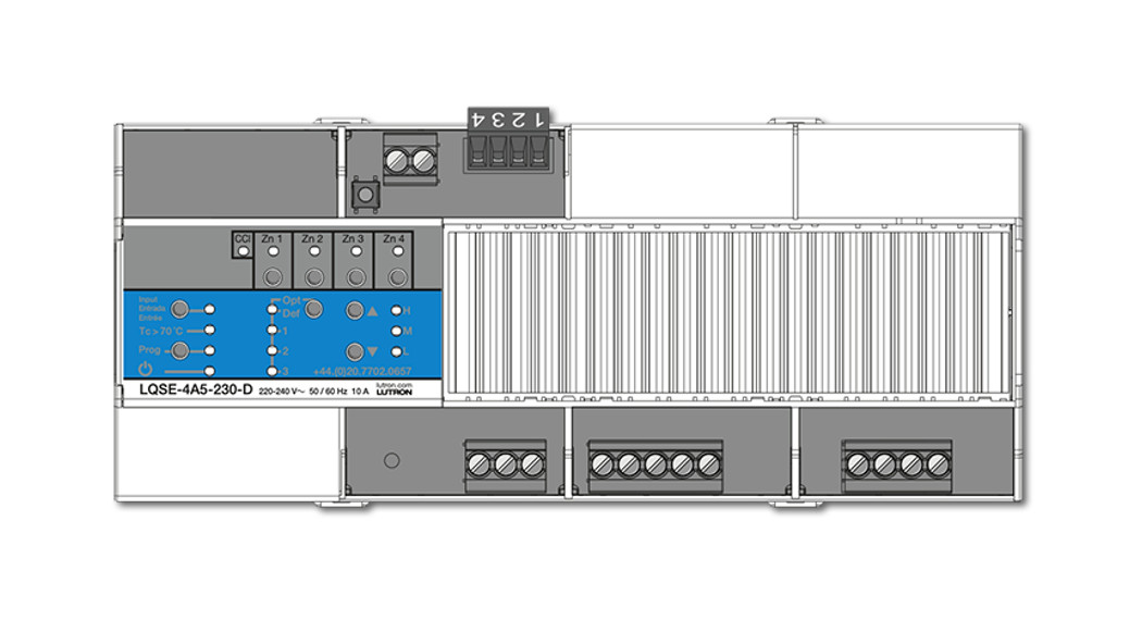
LQSE-4A5-120-D
120 V~ 50 / 60 Hz 16 A

032583 Rev. A05/2021
Numbered illustrations correlate to numbered instructions.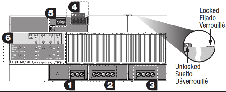


PRO LED+ Phase Adaptive Power ModuleInstall Guide
Please read before installing.
![]() WARNING
WARNING
Shock Hazard. May result in serious injury or death.Turn off power at circuit breaker before installing the unitButtons and LEDs in the unit are used for programming and troubleshooting. If wiring is exposed when accessing buttons and LEDs, the unit must be accessed by a certified electrician, following local codes.Note: For additional information on the unit operation and ratings, please refer to Lutron P/N 3691126 at www.lutron.com.Mounting
- Mount in a Lutron DIN panel (see 3691055 or 3691106) or in an IP20 (minimum) or NEMA Type 1 (minimum) enclosure with an integrated DIN rail (please refer to Lutron P/N 048466 at www.lutron.com).
- Mount with an arrow pointing up to ensure adequate cooling.
- Internal relays make audible noise, mount where acceptable.
- Unit is 12 DIN modules [8.5 in (216 mm)] wide.
Mount to DIN rail by pressing unit onto the rail with clips pressed in. To remove from the rail, pull clips out using a screwdriver.
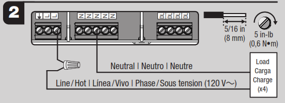
Line Voltage Wiring
- Turn off power and wireline voltage to the unit as shown (DO NOT WIRE LIVE). Terminals will accept 14 AWG to 10 AWG (2.5 mm² to 4.0 mm²) wire.
- Apply power, “u” LED will light if the unit is wired correctly.
Verify Wiring
Follow the steps below to verify there are no faults in the load or wiring.
- Turn off the power (DO NOT WIRE LIVE).
- Wire loads directly to Line / Hot to bypass the unit and protect it from wiring faults.Note: If using a Lutron panel, use the bypass jumper included with the panel.
- Apply power and ensure that the desired loads power on without any faults.
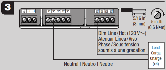
Zone Wiring
| Load Type | Zone 1 | Zone 2, 3 and 4 (per zone) |
| LED (reverse- phase)1 | 6.6 A | 4.2 A |
| Lutron Hi-lume A-series LTE | 4.0 A (20 drivers maximum) | 3.0 A (13 drivers maximum) |
| LED SSL7A-2015 (forward-phase) | 400 W | 200 W |
| Incandescent / Halogen, ELV | 800 W | 500 W |
| Neon / Cold Cathode, MLV | 800 VA (600 W) | 500 VA (380 W) |
Works with all dimmable LED drivers whose inrush current does not exceed NEMA410 standards for electronic ballast/drivers. Refer to www.lutron.com/ledtool for specific LED compatibility information and recommended LED light sources.
• Ratings:Note: Derating may be required depending on panel installation details. For derating information, refer to Lutron product specification (3691126), panel specification (3691055 or 3691106) or DIN panel App Note #466 (048466) at www.lutron.com.
- Turn off power (DO NOT WIRE LIVE).
- Wire loads as shown. Terminals will accept 14 AWG to 10 AWG (2.5 mm² to 4.0 mm²) wire.
- Apply power.
- Note: Operation of a low-voltage circuit with lamps inoperative or removed may result in transformer overheating and premature failure. Lutron strongly recommends thefollowing:a. Do not operate low-voltage circuits without operative lamps in place.b. Replace burned-out lamps as quickly as possible.c. Use transformers that incorporate thermal protection or fused transformer primary windings to prevent transformer failure due to overcurrent.
QS Link (NECR Class 2)
- Turn off power while servicing unit (DO NOT WIRE LIVE).
- Wire QS Link to the unit as shown, note terminals 3 and 4 are twisted, screened pair.Recommended Lutron cable: GRX-CBL-346S for wiring length less than 500 ft (153 m); GRX-CBL-46L for wiring length up to 2000 ft (610 m).
- The link may be daisy-chained or t-tapped, length not to exceed 2000 ft (609 m).
- Do not connect to terminal 2.
Manual Override Contact Closure Input (NECR Class 2)
- If no external override control is required, leave a pre-installed jumper in CCI terminals.
- Turn off power while servicing unit (DO NOT WIRE LIVE).
- Wire CCI as shown using 20 AWG to 10 AWG (0.5 mm² to 4.0 mm²) wire. A single-pole switch(provided by others) must be wired in place of the jumper.
- If opened, the unit will go to manual override light levels and not respond to inputs from other devices.
- When closed or jumpered, the unit will return to the settings or levels they were at prior to entering manual override.
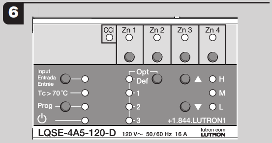
6 LED Diagnostic Indicators
| LED | Behavior | Description |
| Power |
Continuous on | Normal operation |
| Off | General system failure/No power; verify breaker is on | |
| Rapid flash: 10 blinks/sec | Unit failure: contact Lutron | |
| Hi-Temp Tc >70 °C | Off | Normal Operation |
| 1 second on, 7 seconds off | Unit is too hot, loads scaled to 25% power | |
| Continuous on | Unit is too hot, loads turned off | |
| Flashing: 1 blink/sec | The unit was overheated and has now cooled to an acceptable temperature. To clear the error, press the “Input”, “Prog”, “ |
|
| Prog | Off | The device in Normal Mode |
| Flashing: 1 blink/sec | The device in Program Mode | |
| Zone 1-4 | Off | Normal Operation: zone off |
| Continuous on | Normal Operation: zone on | |
| 1 blink, pause | Zone selected for manual control; will timeout after 10 seconds | |
| Output shorted or overloaded: verify wiring | ||
| 2 blink, pause | Overvoltage: verify load type | |
| 3 blink, pause | Shorted component: verify panel jumper/wiring; contact Lutron | |
| 4 blink, pause | Over-temperature: zone may be overloaded, all loads scaled to 25% | |
| 5 blink pause | Over-temperature: zone may be overloaded, all loads turned off | |
| Rapid flash: 10 blinks/sec | Multiple errors: contact Lutron | |
| CCI | Continuous on | Normal operation |
| Rapid flash: 10 blinks/sec | Manual override mode/Contact open/Jumper missing |
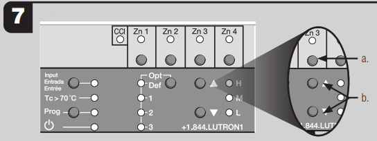
Verify Lights – On / Off
a. “Zn” buttons: Press “Zn” button to select the zone to control.b. “ ![]() ” and “▼” Buttons: Turn loads on and off.Note: Unit will only turn on and off until load type is programmed for dimming.
” and “▼” Buttons: Turn loads on and off.Note: Unit will only turn on and off until load type is programmed for dimming.
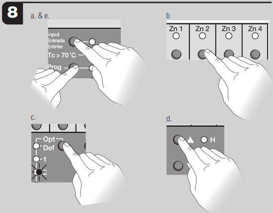
Verify Lights – Dimming (Optional)
Manual Programming Load Typea. Press and hold “Prog” and “Input” button for 3 seconds.b. Press a “Zn” button to select a zone.c. Press “Opt” button repeatedly until Opt 2 is selected.d. Use the “ ![]() ” and “▼” buttons to select desired load type.
” and “▼” buttons to select desired load type.
| Load Types | H: Auto (dim) — Phase-detection |
| M: MLV (dim) — Forward-phase | |
| L: ELV (dim) — Reverse-phase |
Note: All load type settings will be overwritten by HomeWorks programming.Press and hold “Prog” and “Input” button for 3 seconds to exit setup.
Programming
• For programming: Use the HomeWorks Designer software.
FAQs (Frequently Asked Questions)
- Can I use non-dim loads with this product? No, only dimmable loads may be used. Use PHPM-SW-DV-WH if non-dim control is required.
- Can I use LED loads with this product? Yes, Refer to www.lutron.com/ledtool for compatibility with dimmable LED light sources.
- Can I use multiple load types on one zone? No, only one load type may be used per zone.
- Can I control receptacles with this product? No, use PHPM-SW-DV-WH if receptacle control (15 A maximum) is required.
- How do I know if the unit is dimming with forward-phase or reverse-phase dimming? Press the “Opt.” button and look at the “Zn” LEDs:– Solid on = reverse-phase– 1 blink / second = forward-phase
- How do I know if the QS link is working properly? Press the “Opt.” button. If the “ ” LED flutters periodically, the QS link is operating normally. If the “
 ” LED is flashing, there is a communication error or there are no other QS devices on the link.
Customer Assistance | Asistencia al cliente |Assistance à la clientelewww.lutron.com/support
U.S.A. (1.844.LUTRON1)Mexico (+1.888.235.2910)
Others (610.282.3800)
Limited Warranty
[PDF]Lutron and HomeWorks are trademarks of Lutron Electronics Co., Inc., registered in the U.S. and other countries.©2019–2021 Lutron Electronics Inc. Co., Inc.
Help | Ayuda | Aide: www.lutron.com/support 1.844.LUTRON1 (U.S.A)
References
[xyz-ips snippet=”download-snippet”]