
LUTRON QS DIN Rail Panel
Lighting Control Systems
Athena QS DIN Rail Panel
Configurable Lighting Control panels arepre-assembled and tested power panels that are configurable to control multiple load types. Panelsare available with branch circuit breakers or as a feed-through control or satellite panel. The breaker panels come with a branch circuit breaker for each DIN Power Module (DPM). The control panels have a control gear compartment that can house a processor and power supply, and other low voltage gear. Satellite panels replace the control gear compartment with DIN rail rows to mount additional DPMs.
Features
- Panels are pre-wired and tested prior to shipping.
- Feed-through panels and panels with breakers are available.
- Integral Athena Edge processor available.
- Supports various load types using DIN power modules (DPMs):– Switching (QSN-4S8-120-D)– PRO LED+ Phase Adaptive (QSN-4A5-D)– 0–10 V- / Switching control (QSN-4T5-120-D)
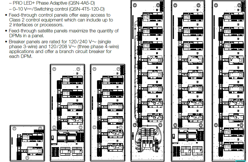
- Feed-through control panels offer easy access to Class 2 control equipment which can include up to 2 interfaces or processors.
- Feed-through satellite panels maximize the quantity of DPMs in a panel.
- Breaker panels are rated for 120 / 240 V~ (single phase 3-wire) and 120 / 208 V~ (three phase 4-wire) applications and offer a branch circuit breaker for each DPM.
- Feed-through panels are rated for 120 / 277 V~ applications.Note: 277 V~ is only supported for phase control loads at this time.
- Easily integrates with Lutron QS devices.
- Scalable from a single area or floor; to a building or whole campus.
- Integral emergency contact closure input (CCI) on each DPM turns all lights on to a programmable level when activated using a LUT-ELI and ensures that the system is compliant with UL 924®.
- Bypass jumpers included for load mis-wire protection.
- Panels are available in three sizes: 16 in (406 mm), 42 in (1067 mm), and 65 in (1651 mm).
- Black, powder coated front cover with vents to maximize thermal performance included.
Specifications
Regulatory Approvals
- cULus®
- NOM
- cULus® Listed to be able to add and replace Lutron DPMs in the field
Power
- Feed-through:
- 120 / 277 V~ 50 / 60 Hz 20 A max per circuit
- Breaker Panel:
- 120 / 240 V~ 50 / 60 Hz (single phase 3-wire)
- 120 / 208 V~ 50 / 60 Hz (three phase 4-wire)
- 15 A or 20 A branch breakers
- 125 A main lugs
- Lightning strike protection: Meets ANSI / IEEE standard C62.41-2000 and IEC 61000-4-5. Can withstand voltage surges up to 6000 V~ and current surges up to 3000 A.
- 10 year power failure memory: restores lighting to levels prior to power interruption.
DIN Modules Available (maximum of 10)
- 120 / 277 V~ PRO LED+ Phase Adaptive
- 120 V~ Switching
- 120 V~ 0–10 V- / Switching
Wiring
- Internal: Wired and tested by Lutron.
- System communications: NEC® Class 2 wiring connects panels to control station. Wired sensors must be wired to QS Sensor Module (QSM).
- Line (mains) voltage: only feed and load wiring required (feed-through panels require feeds for the module power).
Mounting
- Surface- or recess-mount.
Construction
- 16 AWG (1.5 mm) galvanized sheet metal enclosure (unpainted).
- 16 AWG (1.5 mm) powder-coated (black) metal cover with ventilation holes.
Environment
- Enclosure: NEMA Type 1, IP-20 protection.
- Mount where ambient temperature is 32 to 104 °F (0 to 40 ºC). Relative humidity less than 90%, non-condensing.
- Indoor use only.
- Passive cooling (fan is not required)
- DPMs generate heat. See device spec sheet for BTU ratings.
Line Voltage (Mains) Connections
- Feed-through panels
- DIN rail-mounted terminal blocks provided for line-voltage (mains) power to DPMs and to control equipment power supply.
- DIN rail-mounted terminal blocks provided for load wiring. Use copper wire only.
- Breaker panels
- Options available for single phase 3-wire and three phase 4-wire main input. Main lug connections provided for line-voltage (mains) power. Power is distributed to branch circuit breakers, and DPMs via internal wiring installed by Lutron. Use copper or aluminum wire (install and wire in accordance with all local and national codes).
- DIN rail-mounted terminal blocks provided for load wiring. Use copper wire only.
Wire Sizing
- DIN rail-mounted terminal blocks:– Line (mains) and load terminal blocks will accept one 26 AWG to 10 AWG (0.14 mm2 to 6.0 mm2) wire or two 26 AWG to 16 AWG (0.14 mm2 to 1.5 mm2) wires.
- Breaker panel main lugs will accept one 6 AWG to 2 / 0 AWG (16 mm2 to 70 mm2) wire per pole.
Maximum Panel Capacities
- Interfaces or Processors consist of the following:
- QP-2L or QP-1L (Athena Edge Processor)
- QSE-IO (Contact Closure Interface)
- QSE-CI-DMX (DMX Interface)
- QSE-CI-NWK-E (Network Interface)
- Q-POE-8 (8-port PoE Switch)
- DIN Power Modules consist of the following:
- QSN-4A5-D (PRO LED+ Phase Adapative)
- QSN-4S8-120-D (Switching)
- QSN-4T5-120-D (0-10 V / Switching)
System Diagram
Note: 120 V~ output ratings shown are for reference only. Please refer to each DPMs spec sheet for complete zone output ratings. See last page for spec sheet part numbers.
Panel Model Numbers
The following model numbers are non-orderable base models for the factory assembled QS DIN panels and must be configured to order. See Panel Configuration Nomenclature below for all assembly options.PD2-S-ASM: 16 in (406 mm) Satellite Panel with up to 2 DPMsPD4-C-ASM: 42 in (1067 mm) Control Panel with up to 4 DPMs and a low-voltage compartmentPD6-S-ASM: 42 in (1067 mm) Satellite Panel with up to 6 DPMsPD8-C-ASM: 65 in (1651 mm) Control Panel with up to 8 DPMs and a low-voltage compartmentPD8-B-ASM: 65 in (1651 mm) Breaker Panel with up to 8 DPMs and branch circuit breakersPD10-S-ASM: 65 in (1651 mm) Satellite Panel with up to 10 DPMs
Panel Configuration Nomenclature
Note: The following information is given for general use only. Use Lutron Designer+ to configure panel combinations and for assistance with specifying module and control equipment. See page 6 and 7 for example configurations.
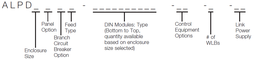
Enclosure Sizes2 = 16 in (406 mm) enclosure (2 DPMs)4 = 42 in (1067 mm) enclosure (4 DPMs)6 = 42 in (1067 mm) enclosure (6 DPMs)8 = 65 in (1651 mm) enclosure (8 DPMs)10 = 65 in (1651 mm) enclosure (10 DPMs)
Panel OptionsB = Breaker Panel (breakers and modules, no control equipment)C = Control Panel (control equipment compartment and modules, no breakers)S = Satellite Panel (modules only, no control equipment or breakers)
Branch Circuit Breaker Options (QTY: 8)15B = 120 V~ 15 A Breakers20B = 120 V~ 20 A BreakersBlank = 120 / 277 V~ Feed-through
Feed TypesL3 = 1 Ø 3 W (125 A main lug, breaker panel only)L4 = 3 Ø 4 W (125 A main lug, breaker panel only)Blank = Feed-through (20 A per feed maximum)
DIN ModulesB = Four Output PRO LED+ Phase Adaptive Dimming F = Four-Circuit SwitchingG = Four-Circuit 0–10 V- / Switching0 = Open space for expansion
Control Equipment Options(maximum of 2, controls panel only)N = 2-Link ProcessorR = 1-Link ProcessorX = DMX ControlC = Contact Closure InterfaceK = Network InterfaceA = PoE Switch0 = Open space for expansion
Wire Landing Boards (1-4, control panels only)_ = # of QS Wire Landing BoardsLink Power Supply (maximum of 2, control panels only)L = 75 PDU Power Supply (required if panel contains processor or PoE Switch)0 = No Power Supply, open space for expansion
Example Configurations
Breaker PanelBase Model: PD8-B-ASM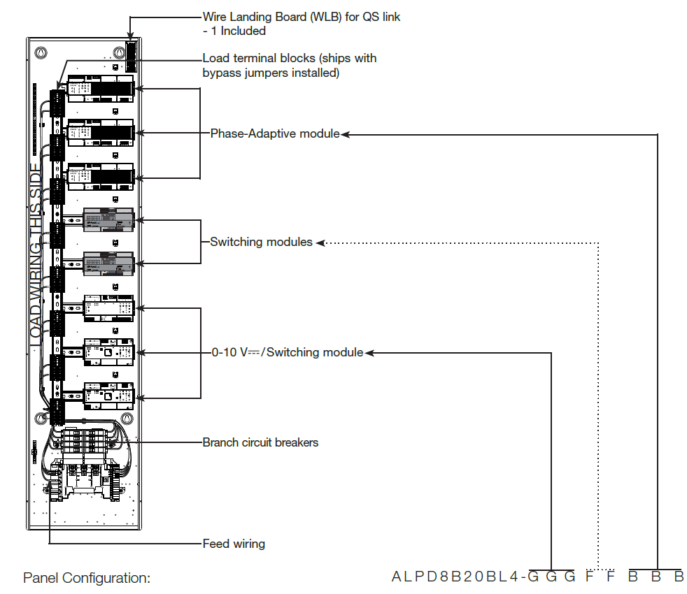
ExampleALPD8B20BL4-GGGFFBBB: 65 in (1651 mm) breaker panel with 20 A branch circuit breakers and 3 Ø 4 W main input with (3) phase adaptive modules, (2) switching modules, (3) 0–10 V- / Switching module.
Feed-Through Control PanelBase Model: PD8-C-ASM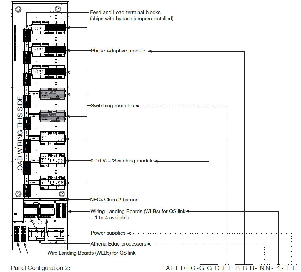
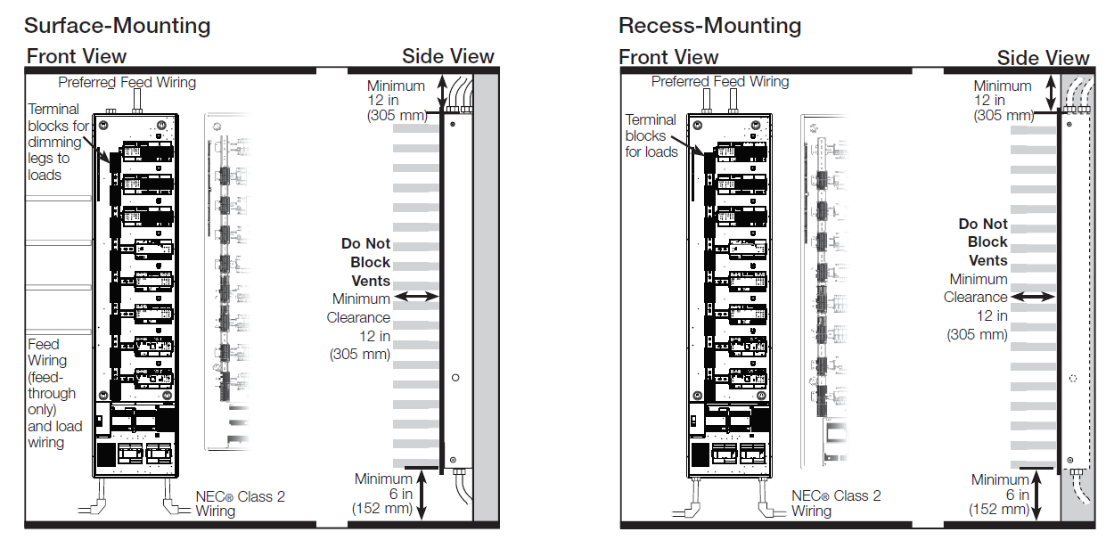
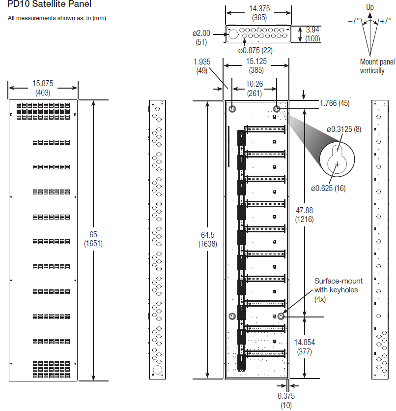
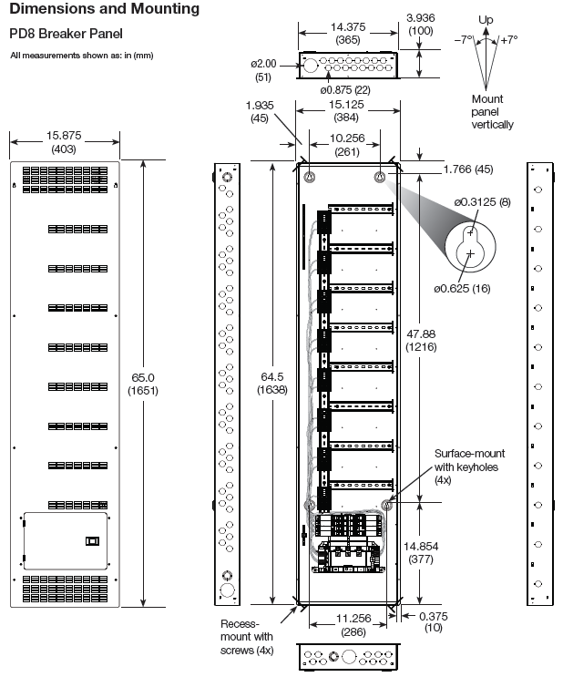
Mounting for Panels
- For indoor use only.
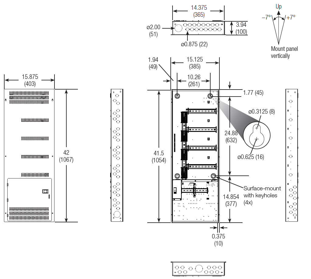
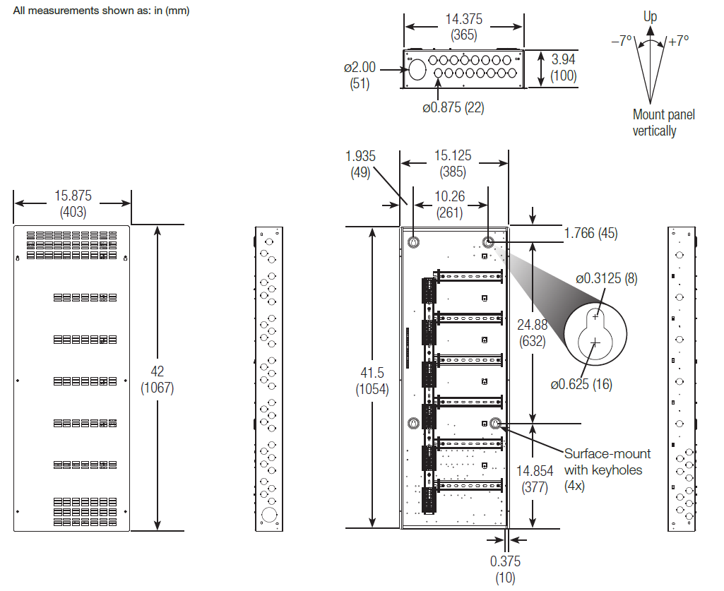
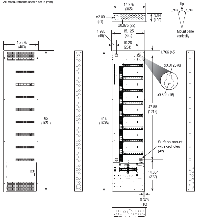
- Consult dimensions page for panel size, conduit knockouts, and mounting hole locations.
- Panels weigh up to 110 lb (50 kg). Reinforce wall structure for weight and local codes.
- Mount panel where audible noise is acceptable.
- This equipment is passively air-cooled. Mount in a location where the vented cover will not be blocked. 12 in (305 mm) of clearance in front of the vents is required. Vents must not be blocked or the warranty will be voided.
- Mount the panel so that line-voltage wiring will be at least 6 ft (1.8 m) from audio and video equipment, or radio frequency devices equipment and wiring.
- For surface mount, mount the panel a minimum of 6 in (152 mm) from the floor and 12 in (305 mm) from the ceiling.
- Mount panel using one of the methods below (mounting hardware is not pro vid ed):
- Lutron recommends using 1/4 in (6 mm) mounting bolts.
- Use keyholes with bolts sufficient for 110 lb (50 kg) load, M6 (1/4 in) bolts rec om mend ed.
- Mount within 7º of true vertical
- Install in accordance with all local and national electrical codes.
- Limit vertical stacking of PD2 panels to three panels high and limit vertical stacking of PD4 panels to two panels high, while maintaining at least 12 in (305 mm) of air space at the top and bottom of each panel. Do not vertically stack PD6, PD8, or PD10 panels.
Recess-Mounting
- Mount panel between flush and 1/8 in (3.2 mm) below finished wall surface.
- Use screws sufficient for 110 lb (50 kg).
Dimensions and Mounting

PD4 Control Panel
PD6 Satellite Panel
PD8 Control Panel
PD10 Satellite Panel
PD8 Breaker Panel
Panel Wiring
Wire Sizes
- Mains Feed (to main lugs, breaker panel only):6 AWG (16 mm2 ) to 2 / 0 AWG (70 mm2)
- Mains Feed (to terminal block):26 AWG (0.14 mm2) to 10 AWG (6.0 mm2)
- Dimmed Line (to terminal block):26 AWG (0.14 mm2) to 10 AWG (6.0 mm2)
- Load Neutral (to terminal block):26 AWG (0.14 mm2) to 10 AWG (6.0 mm2)

Wiring Tips
Wire the panel similar to a Lighting Distribution Panel:
- Run feed and load wiring to appropriate terminal blocks installed in the panel.
- For feed through panels run separate neutrals for each module—no common neutrals across phases.
- The panel can provide temporary lighting:– Wire all loads.– Do not remove bypass jumpers that are pre-installed for load controlling modules.– Use pre-installed breakers to switch lights on and off
NEC® Class 2 Wiring
- NEC® Class 2 wiring is used for all system communications.
- NEC® Class 2 wiring must run in a separate trough from line (mains) voltage.
- Must be less than 2000 ft (600 m) long.
Configurable Link Wiring: QS Devices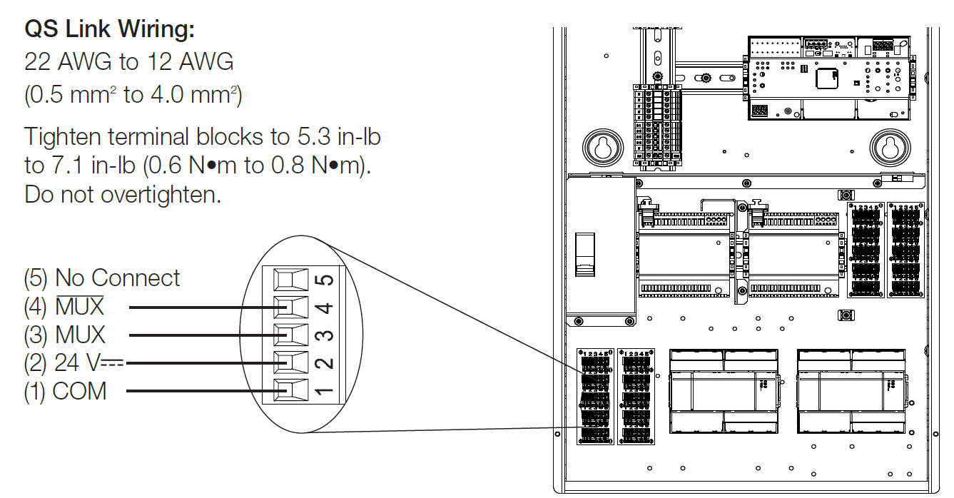
Notes
- System communication uses NEC® Class 2 wiring.
- Follow all local and national electrical codes when installing NEC® Class 2 wiring with line voltage / mains wiring.
- Each terminal accepts up to two 18 AWG (1.0 mm2) wires or one 12 AWG to 22 AWG (4.0 mm2 to 0.5 mm2) wire.
- Make all connections inside the panel.
- Refer to the QS Link Power Draw Units Specification Submittal (Lutron P/N 369405 at www.lutron.com) and the table above for information concerning Power Draw Units (PDUs).
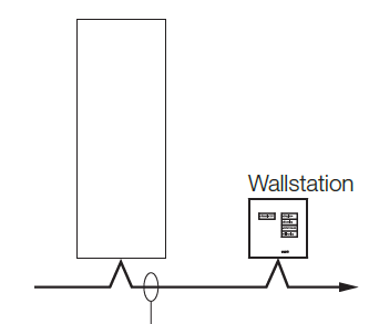
- Wiring can be T-tapped or daisy-chained.
Wiring: QS Link

Athena Security Statement
Lutron takes cybersecurity very seriously. We actively monitor the threat landscape and take a proactive approach to security and privacy, continuously working to update and enhance our systems and processes.At Lutron, we call our approach to cybersecurity “Secure Lifecycle”, and we would like to present the following steps we take to protect your security and privacy:
- Security by Design. When building a new system, Lutron utilizes a dedicated security team to ensure best practices are implemented. Security is built in. It is not an afterthought or an add-on.
- Third-Party Validation. Security is complicated. Lutron has a dedicated team of internal experts, but we also leverage external experts to double-check our work, and to make security recommendations.
- Continuous Monitoring and Improvements. Security is a constantly moving target. Lutron uses a dedicated security team to continuously monitor for potential threats and, when needed, send out security patches to update installed systems.
- Ongoing Support. Lutron has the resources you need to answer questions about security when they arise We incorporate a variety of security features into our product designs. These features include recommendations from the National Institute of Standards and Technology (NIST) among others, and they are aimed at meeting our secure lifecycle protections. While we do not publish a comprehensive list of our security features, the following list is a small example of some of the techniques employed in our system designs for Athena Edge processors, Light Management hubs, Clear Connect – Type X Gateway devices and associated services (such as mobile applications and cloud resources):
- Secure and authenticated remote access with unique keys for every Athena system
- A secure hardware element (“chip”) on all Athena Edge processors and Clear Connect – Type X Gateway to guard the keys used for secure communication and authentication
- Enforcing industry-standard encrypted communication and techniques for our integration protocols to the highest extent possible. Any integrated third-party components or systems should be evaluated independently.
- Secure commissioning – all communication between the system programming software tool / app and the processors is encrypted and authenticated. Programming a system requires permission to access that system.
- Security updates are pushed out automatically to the lighting system for urgent security patches. Lutron is committed to one year of security support from system start-up date.
- Use of industry-standard techniques for cloud-based integrations, such as OAuth2.0
- Signed processor firmware to ensure a firmware update is authentically from Lutron.
If you have additional questions or would like to make a vulnerability disclosure to Lutron, please contact Lutron’s 24/7 Technical support Line at 1.844.LUTRON1 or visit us at [email protected]
The Lutron logo, Lutron, Athena, HomeWorks, Radio Powr Savr, Sivoia, Pico, GRAFIK Eye, LED+, Roller 64, Roller 100, Roller 225, and seeTouch are trademarks or registered trademarks of Lutron Electronics Co., Inc. in the US and/or other countries.iPad is a trademark of Apple Inc., registered in the U.S. and other countries.All other product names, logos, and brands are property of their respective owners.
![]()
[xyz-ips snippet=”download-snippet”]