
LUTRON® QS Wire Landing Board Installation Instructions
Please Read Before InstallingQS-WLB 24 V![]() 3 A
3 A
Important Notes
Environment
Ambient operating temperature: 32 °F to 104 °F (0 °C to 40 °C), 0% to 90% humidity, non-condensing. Indoor use only.
Codes
Install in accordance with all local and national electrical codes.
Installation
![]() WARNING: Shock Hazard. To avoid the risk of electric shock, locate and remove fuse(s) or lock circuit breaker(s) in the OFF position for all circuits entering the panel before proceeding. Wiring with power ON could result in serious injury or death.
WARNING: Shock Hazard. To avoid the risk of electric shock, locate and remove fuse(s) or lock circuit breaker(s) in the OFF position for all circuits entering the panel before proceeding. Wiring with power ON could result in serious injury or death.
Mounting Inside Pre-drilled Enclosure
- Install wire landing board into appropriate location in an enclosure pre-drilled for the QS-WLB, such as the HQ-LV21-120. Press the snap-in standoffs into the enclosure, beginning with the standoffs on the four corners of the board. A 1/4 in (7 mm) nut driver can be used to help press in the standoffs. Consult the installation instructions for the enclosure to determine the proper location.
Alternate Mounting
The QS-WLB can be mounted in other enclosures that have not been predrilled for the QS-WLB. These enclosures must have a flat mounting surface from 0.050 in (1.3 mm) to 0.062 in (1.6 mm) thick, and must provide at least 0.150 in (3.8 mm) of clearance behind the mounting surface.
- Using the template provided (see Figure 1), drill the mounting holes. Using a No. 22 drill bit (0.157 in or 5/32 in (4 mm) diameter), drill the 6 mounting holes as indicated on the template.
- Attach the QS-WLB to the enclosure. Press the plastic standoffs into holes drilled in the enclosure. Align and press the QS-WLB onto the standoffs mounted in the enclosure.
Wiring
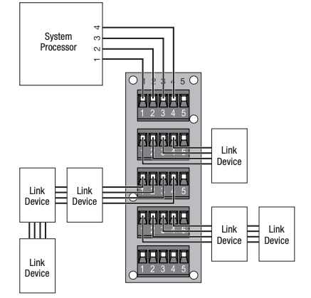
1. Connect communications wires. Connect link wiring to the removable terminal blocks, using terminals 1,2,3, and 4 (see Figure 2). Terminal 5 is typically not used–refer to the installation instructions for the device being connected to determine if terminal 5 is to be used. Tighten terminal blocks to 3.5 in·lb to 5 in·lb (0.4 N·m to 0.57 N·m). Do not overtighten.
Figure 1 — Drill Template

Figure 2 — Link Device Wiring Diagram
Warranty: For warranty information, please see the Warranty enclosed with the product, or visit www.lutron.com/resiinfo
Technical Assistance:U.S.A. / Canada: 1.800.523.9466Mexico: +1.888.235.2910Other Countries: +1.610.282.380024 hours/7 days
Lutron Electronics Co., Inc.7200 Suter RoadCoopersburg, PA 18036-1299P/N 041-295 Rev. A 07/2011
Lutron and the sunburst logo are registered trademarks of Lutron Electronics Co., Inc.© 2011 Lutron Electronics Co., Inc.
References
[xyz-ips snippet=”download-snippet”]