![]()
Radio Power Save
Instructions
Pre-Installation
A Before associating the sensor, install the corresponding dimming or switching device(s).B Twist and remove the mounting bracket to insert the battery into the battery cavity.C Associate sensor with a corresponding dimming or switching device/system.D Before mounting the sensor, please note the following sensor placement information:
- The sensor is designed for ceiling use only. DO NOT install on ceilings higher than 12 ft (3.7 m).
- The sensor should be installed in a location where it has a good view of all parts of the room. The sensor requires line-of-sight to operate properly. If you cannot see thesensor, it cannot see you. The sensor cannot see through glass objects such as patio or shower doors.
- DO NOT mount the sensor within 4 ft (1.2 m) of HVAC vents, halogen or incandescent light bulbs, microwave ovens, Wi-Fi routers, IoT cameras, or other non-clear Connect wireless devices. When using Clear Connect – Type X lamps or fixtures, ensure the sensor is mounted at a distance of 2 ft (0.6 m) or greater from the lamp or fixture.
- The sensor may be installed up to 60 ft (18.3 m) away from the associated dimming or switching device(s) if they are in direct line of sight. If there are walls or other barriers between the sensor and receiving device(s), the sensor should be located within 30 ft (9.1 m).
- Whenever possible, avoid placing the sensor in a location where it has a broad view outside of the intended space. If this is unavoidable, the lens can be masked toblock the view of undesired areas.
Installation
Mounting
- Drop-Ceiling Mounting
 a Place the mounting wire through the mounting bracket and pierce ceiling tile in the desired location. From the opposite side of the tile, slip the Ceiling Tile Backer through both legs of the wire.b, Twist the wire tightly to prevent sensor sagging. The Ceiling Tile Backer will prevent the tile from breaking.
 - Solid-Ceiling Mountinga Drill two 3/16 in (4.6 mm) pilot holes for the provided screw anchors.b Press the anchors into the holes and tap flush with a hammer.c Place the flat side of the mounting bracket against the ceiling and install the two provided screws using a hand screwdriver.d Attach the sensor to the mounting bracket by inserting and twisting in a clockwise direction until the sensor locks into place.
Testing Sensor Coverage
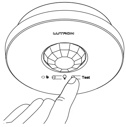
- With the sensor mounted on the ceiling, press and release the “Test” button. The lens will glow briefly, indicating the test mode has been entered.NOTE: There is a warm-up period of 90 seconds after the battery is installed before the test mode is activated. If the button is pressed during this time, the lens will flash continuously until the warm-up period is complete, and then the test mode will be automatically entered.
- Confirm the coverage area by walking through the space and observing the lens. The lens will glow solid every time motion is detected. If the lens remains off during motion, the sensor cannot detect motion at that location.
- Press and release the “Test” button again to exit the test mode. If the button is not pressed, the test mode will automatically time out 15 minutes after being enabled, or 5 minutes after the last detected motion if the room is vacated.
- If the sensor has significant trouble detecting motion during the test, it should be moved to another location and re-tested.
Testing Wireless Communication
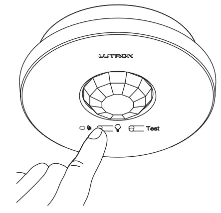
This test should be performed to verify that the sensor has been correctly set up with the corresponding dimming or switching device and that there is proper wireless communication from the chosen sensor location.Press and release the “g” button multiple times to toggle the lights on and off.
Advanced Set-Up
The sensor features several advanced set-up modes. For the majority of installations, the default settings will provide the best performance and you will not need to utilize the advanced setup. If you determine the default settings require adjustment, refer to the back of the sensor. The sensor has three adjustable advanced set-up modes: Auto-On, Activity, and Timeout. The default settings are listed below.
 |
|
|
|
|
Auto-On |
Activity |
Timeout |
|
| Enabled | 30 min | |
|
| Low Light | 15 min | |
|
| Disabled | 5 min | |
|
Default Settings |
|
| Auto-On | Enabled |
| Activity | |
| Timeout | 15 minutes |
Advanced Set-Up ModesAuto-On
The automatic-on functionality of the sensor can be adjusted to control how the lights respond upon initial occupancy. There are three available settings: Enabled, Low Light, and Disabled.Enabled: The lights will always turn on.Low Light: The lights will only turn on automatically if there is not already sufficient ambient light in the room.Disabled: This setting converts the sensor to vacancy-only mode. The lights will not automatically turn on but will still automatically turn off after vacancy. The lights must be manually turned on by using the associated dimming or switching device.
ActivityThe sensitivity of the sensor can be adjusted based on the expected level of activity within the area. There are three available activity settings: Low Activity, Medium Activity, and High Activity.Low Activity: This is the most sensitive setting and will detect very slight motions. This is the recommended setting, as it will work well for nearly all applications. It is ideal for spaces where occupants will often be seated for long periods of time.Medium Activity*: This setting is slightly less sensitive than the Low Activity setting and can be used for spaces that experience normal activity.High Activity*: This is the least sensitive setting and can be used for spaces that will generally only experience large motions, such as foot traffic.
TimeoutThe sensor will turn the lights off if no motion occurs for the duration of the timeout period. There are four available timeout settings: 1**, 5, 15, and 30 minutes.
The Low Activity setting is the default and will perform best for most applications. Rarely, if the sensor is placed near external noise sources such as heating vents, air conditioning vents, or light bulbs, it may turn the lights on without occupancy or keep the lights on too long after vacancy. If this occurs, change the sensitivity to Medium Activity or High Activity to resolve the problem.
To select a 1-minute timeout, press and hold the timeout button for approximately 10 seconds until all three LEDs begin flashing rapidly. To save the 1-minute timeout setting, press and hold the timeout button until all three LEDs turn on solid, indicating the 1-minute timeout has been saved.
Sensor Detection Range
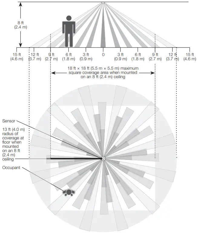
Sensor Coverage Chart (for sensor mounted in the center of the area)
| Ceiling Height | Maximum Square Coverage Area | |
| 8 ft (2.4 m) | 18 ft x 18 ft (5.5 m x 5.5 m) | 324 ft2 (30.2 m2) |
| 9 ft (2.7 m) | 20 ft x 20 ft (6.1 m x 6.1 m) | 400 ft2 (37.2 m2) |
| 10 ft (3.0 m) | 22 ft x 22 ft (6.7 m x 6.7 m) | 484 ft2 (44.9 m2) |
| 12 ft (3.7 m) maximum | 26 ft x 26 ft (7.9 m x 7.9 m) | 676 ft2 (62.4 m2) |
Troubleshooting
| Symptom | Possible Cause | Solution |
| Lights do not turn ON when space is occupied. | The sensor is not correctly associated with dimming/switching device(s). | Refer to Pre-Installation: C |
| The auto-On setting is set to “Low light” or “Disabled* | Refer to Advanced Set-Up | |
| The lights were recently turned off manually and the timeout has not yet expired. | Refer to Frequently Asked Questions at wwwrlutron.com/occsensors | |
| The sensor does not have a full view of the room. | Refer to Sensor Detection Range | |
| The sensor is outside the wireless range of the dimming/switching device. | Refer to Pre-Installation: D or to 3: Testing Wireless Communication | |
| The battery has been installed incorrectly. | Refer to Pre-Installation: B | |
| The dimming/switching device has been improperly wired. | Refer to the instruction sheet of the dimming/switching device a call Ultra Customer Assistance | |
| Light bulb(s) burned out. | ||
| The breaker is off or tripped. | ||
| Lights turn OFF while space is occupied. | Timeout is too short for this application. | Refer to Advanced Set-Up |
| The sensor does not have a full view of the room. | Refer to Sensor Detection Range | |
| Lens mask is improperly applied. | Adjust lens masking | |
| The activity setting is too low. | Refer to Advanced Set-Up | |
| Lights stay ON after space is vacated. | Timeout has not yet expired. | Refer to Advanced Set-Up |
| An external noise source (e.g., an HVAC vent) is interfering. | Try moving the Sensor to a new location or reducing sensitivity. Refer to Pre-Installation: D or to Advanced Set-Up | |
| The battery has been installed incorrectly. | Refer to Pre-Installation: B | |
| Lights turn ON when walking past the room. | Sensor coverage extends beyond the room perimeter. | Refer to Pre-Installation: D |
| The behavior of lights does not match sensor settings. | The intended setting was not saved. | Refer to Advanced Set-Up |
| Multiple sensors are associated with a dimming/switching device and their settings do not match. | Refer to Advanced Set-Up | |
| The sensor lens does not glow in response to motion during Sensor coverage testing. | The sensor cannot see motion due to obstruction. | Move Sensor to another location. Refer to Sensor Detection Range |
| The room is too big or oddly shaped. | Multiple Sensors may be necessary for this room coverage. Refer to Frequently Asked Questions at www.lutron.com/occsensas | |
| The battery has been installed incorrectly. | Refer to Pre-Installation: B | |
| The lens does not stop glowing during sensor coverage testing even when there is no motion. | An external noise source such as an HVAC vent is interfering. | Try moving the Sensor to a new location or reducing sensitivity. Refer to Pre-Installation: D or to Advanced Set-Up |
| Lights do not respond correctly during wireless communication testing. | The sensor is not correctly added to the dimming/switching device. | Refer to Pre-Installation: C |
| The sensor is outside the wireless range of the dimming/switching device. | Move the Sensor closer to the dimming/switching device and retry the test. Refer to 3: Testing Wireless Communication | |
| The battery has been installed incorrectly. | Refer to Pre-Installation: B | |
| The dimming/switching device has been improperly wired. | Refer to the instruction sheet of the dimming/switching device a call Ultra Customer Assistance | |
| Light bulb(s) burned out. | ||
| The breaker is off or tripped. | ||
| Sensor lens flashes and lights do not turn ON when space is occupied. | The battery is low. | Replace battery. Refer to Frequently Asked Questions at www.Lutron.ccm/OCCsensors |
| The sensor is in test mode. | Remove Sensor from test mode. Refer to 2: Testing Sensor Coverage |
Wireless Battery-Powered Occupancy Sensor
Installation InstructionsPlease Read Before Installing
 P/N 041755 Rev. A 05/2020
LRF3-OCR2B-P
| Occupancy / Vacancy | 3 V |
LRF4-OCR2B-P
| Limited Channel Occupancy / Vacancy | 3 V |
LRF5-OCR2B-P
| Occupancy / Vacancy | 3 V |
LRF7-OCR2B-P
| Limited Channel Occupancy / Vacancy | 3 V |
Compatible Products / Additional Information
For a full list of compatible dimming or switching devices and other additional information, visit www.lutron.com/globalenergysolutions
For more information on sensor placement and coverage, temporary mounting, and frequently asked questions, visit www.lutron.com/occsensors and select your product.
Product Description
Lutron ceiling-mounted occupancy sensors are wireless, battery-powered, passive infrared (PIR) devices that automatically control lights via RF communication with a dimming or switching device.
Grace Period
In vacancy mode (Auto-On, disabled) there is a built-in 15-second vacancy grace period that begins when the lights are automatically turned off, during which the lights will automatically turn back on in response to the motion. This grace period is provided as a safety and convenience feature in the event that the lights turn off while the room is still occupied so that the user does not need to manually turn the lights back on. After 15 seconds, the grace period expires and the lights must be manually turned on.
NOTE: The lights can be manually turned off at any time by using the receiving device directly. If the lights are turned off manually, the room must be unoccupied for the duration of the timeout period of the Sensor before the lights will turn back on in response to occupancy.
Important Notes
- This sensor is part of a system and cannot be used to control a load without a compatible dimming or switching device. Refer to the instruction sheets of the receiving device(s) for installation information.
- Clean sensor with a soft damp cloth only. DO NOT use any chemical cleaners.
- The sensor is intended for indoor use only. Operate between 32 °F and 104 °F (0 °C and 40 °C).
- DO NOT paint the sensor.
- Use only high-quality lithium batteries, size CR123, 3 V- (ANSI-5018LC, IEC-CR17345). DO NOT use rechargeable batteries. Using improperly-rated batteries could damage the sensor.
- The range and performance of the RF system is highly dependent on a variety of complex factors such as:
- Distance between system components
- The geometry of the building structure
- Construction of walls separating system components
- Electrical equipment located near system components
NOTICE: DO NOT disassemble, crush, puncture, or incinerate batteries. DO NOT dispose of batteries in normal household waste. Please recycle, take to a proper battery disposal facility, or contact your local waste disposal provider regarding local restrictions on the disposal or recycling of batteries.
 CAUTION: Risk of Fire, Explosion, And Burns. Do not recharge, disassemble, heat above 200 °F (100 °C), or incinerate. This product contains a lithium battery. The battery in this device contains Perchlorate Material — special handling may apply. For more information visit www.dtsc.ca.gov/hazardouswaste/perchlorate
WARNING: Entrapment hazard. To avoid the risk of entrapment, Serious Injury, or Death, these controls must not be used to control equipment that is not visible from every control location or which could create hazardous situations such as entrapment if operated accidentally. Examples of such equipment which must not be operated by these controls include, but are not limited to motorized gates, garage doors, industrial doors, microwave ovens, heating pads, etc. It is the installer’s responsibility to ensure that the equipment being controlled is visible from every control location and that only suitable equipment is connected to these controls. Failure to do so could result in serious injury or death.
Sensor Operation
The sensor will automatically turn the lights ON when the space is occupied and automatically turn the lights OFF after the space is vacated.

Lutron Electronics hereby declares that LRF3-OCR2B-P is in compliance with the essential requirements and other relevant provisions of Directive 1999/5/EC. A copy of the DoC can be obtained by writing to Lutron Electronics Co., Inc. 7200 Suter Road, Coopersburg, PA 18036 U.S.A.
Customer AssistanceFor questions concerning the installation or operation of this product, call the Lutron Customer Assistance. Please provide exact model number when calling.
European HeadquartersUnited Kingdom: +44. (0)20.7680.4481 or 0800.282.107
Asian HeadquartersSingapore: +65.6220.7680.4666 or 800.120.4491
Other countries +1.610.282.3800
Limited Warranty
Lutron EA Ltd. (“Lutron EA”) warrants each unit to be free from defects in material and workmanship and to perform under normal use and service. To the extent permitted by law, Lutron EA and Lutron Electronics Co. Inc. (“Lutron”) make no warranties or representations as to the units except as set forth herein. This warranty shall run for a period of five years from the date of purchase and Lutron’s obligations under this warranty are limited to remedying any defect, replacing any defective part or replacement (at Lutron EA’s sole option), and shall be effective only if the defective unit is shipped to Lutron EA postage prepaid within 60 months after purchase of the unit. Repair or replacement of the unit does not affect the expiry date of the warranty. This warranty does not cover damage or deficiencies due to abuse, misuse, inadequate wiring or insulation or use or installation other than in accordance with instructions accompanying the unit. To the extent permitted by law, neither Lutron EA nor Lutron shall be liable for any other loss or damage including the consequential or special loss or damages, loss of profits, loss of income, or loss of contracts arising out of or relating to the supply of the unit or the use of the unit and the purchaser assumes and will hold harmless Lutron EA and Lutron in respect of all such loss or damage. Nothing in this warranty shall have the effect of limiting or excluding Lutron EA’s or Lutron’s liability for fraud or for death or personal injury resulting from its own negligence, or any other liability, if and to theextent that the same may not be limited or excluded as a matter of law. This warranty does not affect the statutory rights of consumer purchasers of this product. Although every attempt is made to ensure that catalog information is accurate and up-to-date, please check with Lutron EA before specifying or purchasing this equipment to confirm availability, exact specifications, and suitability for your application.
 report this ad
Lutron, Clear Connect, and Radio Powr Savr are trademarks or registered trademarks of Lutron Electronics Co., Inc. in the US and/or other countries.All other product names, logos, and brands are the property of their respective owners. © 2016 – 2020 Lutron Electronics Co., Inc.
TRAREGISTERED NO:ER37418/15DEALER NO:0016561/08
Lutron Electronics Co., Inc.7200 Suter RoadCoopersburg, PA 18036-1299, USA
References
[xyz-ips snippet=”download-snippet”]