LUTRON Vive PowPak Phase Select Dimming Module
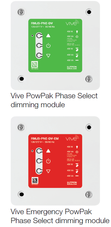
Vive PowPak Phase Select Dimming Module
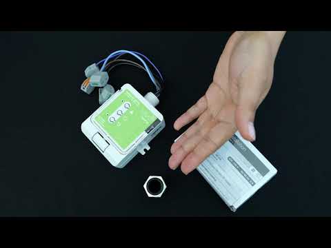
The Vive PowPak Phase Select Dimming Module is a remote-mountable, radio-frequency (RF) dimmer that can operate independently or as a part of a Lutron Vive system. This PowPak module features PRO LED+ technology enabling dimming control in either forward- or reverse-phase down to as low as a 1% light level.
The versatility of the module makes it the ideal lighting control for areas such as classrooms, conference rooms, restaurants, lobbies, and retail.
The module is part of the Lutron Vive system and is compatible with Lutron RF input devices such as Pico remote controls and Radio Powr Savr sensors. This is accomplished by using Lutron Clear Connect – Type A RF Technology.
These modules are also compatible with the Vive hub which enables an app-based simple setup process using a standard web browser on any Wi-Fi enabled phone, tablet or computer. The Vive hub also enables control and monitoring of all Vive devices and can be added at any time (system reprogramming will be required). For a complete list of features supported with the Vive hub, see specification submittal 369902 at www.lutron.com
Models
| Model Number | Region | Operating Voltage | Frequency Band |
| RMJS-PNE-DV | U.S.A., Canada, Mexico | 120 / 277 V~ | 431.0 –437.0 MHz |
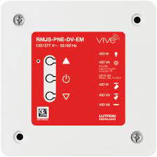
| RMJS-PNE-DV-EM | U.S.A., Canada, Mexico | 120 / 277 V~ | 431.0 –437.0 MHz |
Features
- 120 / 277 V~ voltage phase control for various phase dimmable fixture types (see page 4):
- Screw-in LED bulbs
- Retrofit LED bulbs
- LED fixtures with phase control drivers
- Fluorescent 2-wire fixtures
- Track-lighting (ELV, MLV)
- Neon/cold cathode light (with step-up phase control transformers)
- PRO LED+ is Lutron’s industry-leading technology which enables either forward or reverse-phase control for optimal dimming down to as low as 1% (dependent on the driver’s capabilities).
- Phase selectable (non-automatic): Operates in reverse-phase mode by default. Can be changed to forward-phase mode using button presses or the Vive app.
- Plenum rated.
- Model (RMJS-PNE-DV-EM) available for use with emergency lighting. See page 6 for operating details. 1
- Configurable high- and low-end trim.
- RTISS technology compensates for incoming line variations such as frequency shifts (up to +/- 2%change in frequency / second), harmonics and line noise.
- Flexible installation. Can be mounted horizontally or vertically.
- RTISS-ICM technology is able to withstand high inrush LEDs, bulb blowouts, and direct shorts.
- Integral protection for common temporary over-current and over-voltage conditions.
- LEDs on the PowPak module provide diagnostic information. See App Note #781 (P/N 048781) on www.lutron.com for more information.
- Buttons on the PowPak module provide override control.
- 10-year power failure memory automatically returns the outputs to the levels they were set to prior to a power outage.
- NEMA SSL 7A-2015 compliant for compatibility with solid state lighting.
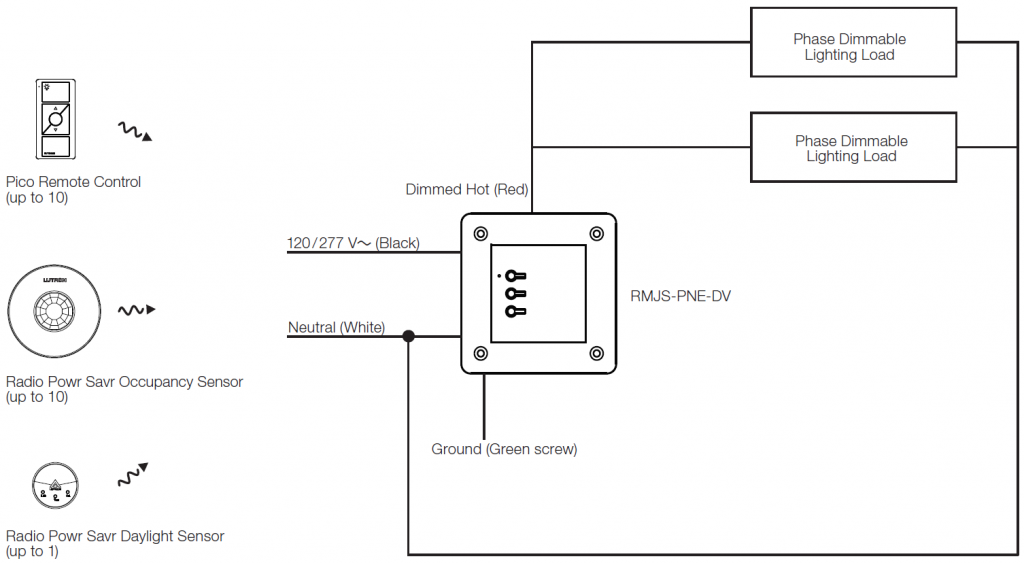
- Receives wireless inputs from up to 10 Pico remote controls, 10 Radio Powr Savr occupancy / vacancy sensors, and 1 Radio Powr Savr daylight sensor Utilizes Lutron Clear Connect – Type A RF Technology (see frequency range on page 2).
- Mounts in a standard metal 4 in x 4 in (101.6 mm x 101.6 mm) junction box.
For more information, see the following documents:Application note: [PDF]Installation guide: [PDF]
1 See App Note #628 (P/N 048628) on www.lutron.com for emergency lighting applications.
Specifications
Regulatory Approvals
- cULus 508 Listed
- Complies with the limits for a Class B device, pursuant to IC and FCC rules
- Plenum-rated:Complies with requirements for use in other spaces used for environmental air (plenums) per NEC® 2014 300.22(C)(3)
- Listed in accordance to CAN / ULC S142 standard method of fire test for heat and visible smoke release for discrete products
- NEMA SSL 7A-2015
- UL® 924 (RMJS-PNE-DV-EM only).
- NOM certified for MexicoPower
- Operating voltage 120 / 277 V~ 50 / 60 Hz
- 0 W minimum loadOutput Ratings
- Output must not be used to control receptacles.
- Output must be directly connected to the load.
- Output breakers or switches must not be used.Other Power Specifications
- Standby power:
- 120 / 277 V~ 650 mW typ.
- BTU / hour when fully loaded: 23 max.
- Works up to the output current rating with all dimmable LED drivers whose inrush current does not exceed NEMA 410-2015 standards for electronic ballast/driver.
- For applications requiring higher wattage ratings, use a power booster (PHPM-PA-120-WH, PHPM-PA-DV-WH, or PHPM-PA-277 / DV). Note: The Vive PowPak phase select dimming module must be set to forward-phase when used with these interfaces.
- For applications requiring 0–10 V- control, use a 10 V interface (GRX-TVI).
- For applications using Lutron 3-wire fluorescent dimming ballasts or 3-wire LED drivers, use the PHPM-3F-120-WH or PHPM-3F-DV-WH. See https://www.lutron.com/TechnicalDocumentLibrary/ 369- 355.pdf for more details.
(for both RMJS-PNE-DV and RMJS-PNE-DV-EM)120 V~ Ratings:
| Load Type | Phase Control | Rating (maximum) | Example Light source/fixture |
| LED driversI | Reverse-phase | 450 VAF | LED downlights (or other LED fixtures) driven by reverse-phase LED driver, unless other wise specified |
| LED bulbs with integral driver I | Reverse-phase | 450 VAF, G | LED retrofit bulbs (with Edison-Screw base, G24, Bi-pin or other base types) driven by reverse phase, unless otherwise specified |
| Lutron LTEA Hi-lume 1% 2-wire LED driver A | Forward-phase | 3 A (13 drivers max) | LED downlights, LED troffer, LED linear pendant, and LED linear recessed, etc., driven by Lutron Hi-lume LED driver |
| LED NEMA SSL 7A-2015 B, H | Forward-phase | 200 W | Screw-in dimmable LED bulbs rated NEMA SSL7 |
| Incandescent / halogen | Either | 450 W | Line-voltage tungsten filament lamps, including line-voltage (120 V~) halogen lamps |
| ELV | Reverse-phase | 450 W | Low-voltage track lights / spots / strip fixtures with AR111, MR16, MR11, PAR36 etc., powered by electronic (solid state) transformer |
| Two-Wire Fluorescent | Forward-phase | 400 VAF | Fluorescent lighting fixtures driven by Tu-wire and Advanced Mark X dimmable ballasts |
| Neon / Cold Cathode, MLV C ,D | Forward-phase | 400 VAF (320 W) E | Low-voltage track lights / spots / strip fixtures with magnetic (core and coil toroidal) transformer supplied low-voltage lighting (6, 12, and 24 V~) |
277 V~ Ratings:
| Load Type | Phase Control | Rating (maximum) | Example Light source/fixture |
| LED bulbs with integral driver I | Reverse-phase | 450 VAF | LED downlights, LED troffer driven by reverse-phase LED driver unless otherwise specified |
| Incandescent / halogen | Either | 450 W | Line-voltage tungsten filament lamps, including line-voltage (277 V~) halogen lamps |
| ELV | Reverse-phase | 450 W | Low-voltage track lights / spots / strip fixtures with AR111, MR16, MR11, PAR36 etc., powered by electronic (solid state) transformer |
| Fluorescent | Forward-phase | 400 VAF | Fluorescent lighting fixtures driven by Tu-wire and Advanced Mark X dimmable ballasts |
| Neon / Cold Cathode, MLV C ,D | Forward-phase | 400 VAF (320 W) E | Low-voltage track lights / spots / strip fixtures with magnetic (core and coil toroidal) transformer supplied low-voltage lighting (6, 12, and 24 V~) |
| Forward-Phase LED, LED NEMA SSL7 | Forward-phase | 277 V~ not supported | Interface required J |
A Load type must be set to forward-phase with low-end trim = 32% and high-end trim = 78%. Setting the proper trim and load type is necessary to ensure optimal performance and 1% dimming capability.B Complies with NEMA SSL 7A-2015 when configured in Vive UI application to LED forward-phase with low-end trim set to 12% and high-end trim set to 90%.C MLV is forward-phase only.D Only use iron / steel (core and coil, magnetic) transformers intended for use with an electronic switch or dimmerE Actual lamp wattage.F Rating based upon input to the converter (MLV transformer, LED driver, or fluorescent ballast). Actual lamp wattage will be less depending on efficiency of the converter. Contact manufacturer or consult data sheets for values.G RMS current should not exceed 3.75 A.H See https://www.lutron.com/TechnicalDocumentLibrary/048637.pdf for more information. Dimming LEDs in forward-phase have reduced ratings compared to reverse-phase due to higher peak currents.I Works with all dimmable LED drivers whose inrush current does not exceed NEMA410 standards for electronic ballast/drivers.J Forward-phase at 277 V~ requires a PHPM interface. In Lutron Designer+, PHPM will be added regardless of load size if forward-phase is chosen for LED at 277 V~.
Mounting
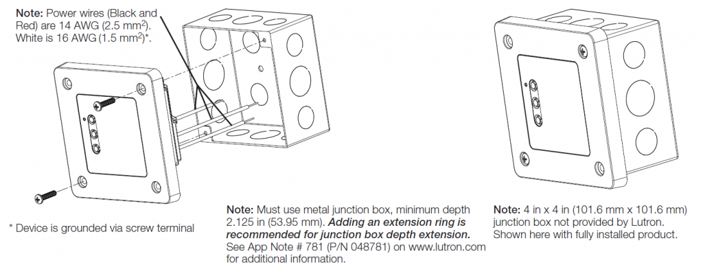
- This device must be fully installed into a metal junction box using two screws. The device must be mounted such that the backcover is inside the 4 in x 4 in (101.6 mm x 101.6 mm) junction box and the front faceplate is outside the 4 in x 4 in (101.6 mm x 101.6 mm) junction box. Adding an extension ring is recommended for junction box depth extension.
- Improper installation can result in degraded wireless communications and intermittent or sustained communications failures and will not be covered under warranty. For all other installations, refer to the installation instructions and consult local and national electric codes for proper installation.
- The front of the PowPak module needs to be accessible for some programming steps.Record where it is mounted so that it can be easily located later.
- Can be mounted in any orientation.
System Communication
- Operates using Clear Connect – Type A RF Technology for reliable wireless communication; refer to model number chart on page 2 for frequency band details.
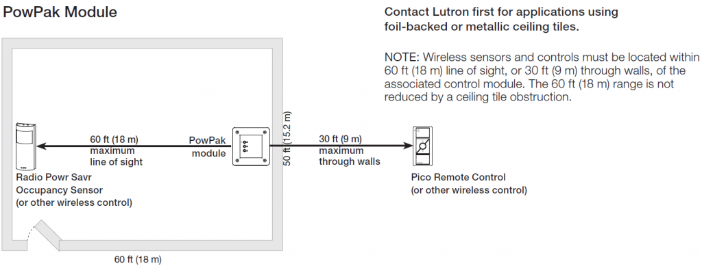
- Wireless sensors and controls must be located within 60 ft (18 m) line of sight, or 30 ft (9 m), through walls, of the associated control module. The 60 ft (18 m) range is not reduced by a ceiling tile obstruction. Contact Lutron first for applications using foil-backed or metallic ceiling tiles.
Environment
- Ambient operating temperature:32 °F to 104 °F (0 °C to 40 °C)
- 0% to 90% humidity, non-condensing
- For indoor use only
Default Operation
- Associated wireless input devices control all connected fixtures together
- Occupancy sensors:
- Occupied: 100%; Unoccupied: 0% (OFF)
- Pico remote controls:
- On: 100%; Favorite Level: 50%; OFF: 0% (OFF)
- Daylight sensor: Decreases electric light in response to additional available daylight
Key Design Features
- LED status indicator shows RF communication, error codes, and provides programming feedback. See App Note #781 (P/N 048781) on www.lutron.com for more details.
- Configurable high-end and low-end trim
- 10-year power failure memory: If power is interrupted, connected loads will return to the level prior to interruption
- The OFF level (minimum light level) can be set in standalone (non-hub) mode to either low-end or OFF. Additional options available via the Vive app.
- 1 year limited warranty. The customer can register the product to increase the warranty period from 1 year to 5 years. Please visit www.lutron.com/warranty for warranty details.
RMJS-PNE-DV-EM Sequence of Operation With a Vive hub:
- Normal mode: The RMJS-PNE-DV-EM can dim loads as normal and respond to local button presses, Pico remote controls, occupancy sensors, daylight sensors, timeclock events and preset scene calls.
- Emergency mode: Upon loss of power greater than 250 mS OR an override signal* from the Vive hub, the RMJS-PNE-DV-EM will override the light output to its emergency level (configured using the Vive hub) and enter lockout mode. It will not respond to any local button presses, Pico remote controls, occupancy sensors, daylight sensors, timeclock events, or preset scene calls.
- Return from Emergency mode to Normal mode: When normal power is restored to the Vive hub or the override signal* from the Vive hub is cleared, the emergency PowPak module will return to the previous light level between 3 and 10 minutes of normal power being restored. It will again respond to local button presses, Pico remote controls, occupancy sensors, daylight sensors, timeclock events, and preset scene calls.
- Override signal triggered from the contact closure #2 on the Vive hub from one of the following inputs:
- Fire alarm control panel
- Security system
- LUT-ELI-3PH
Without a Vive hub:
- Normal mode: The RMJS-PNE-DV-EM can dim loads as normal and respond to local button presses, Pico remote controls, occupancy sensors, and daylight sensors.
- Emergency mode: When the RMJS-PNE-DV-EM is powered up after a loss of power greater than 250 mS the RMJS-PNE-DV-EM will override the light output to full and enter lockout mode for 90 minutes. It will not respond to any local button presses, Pico remote controls, occupancy sensors or daylight sensors.
- Returning from Emergency mode to Normal mode: When normal power is restored, the emergency PowPak module will remain in emergency mode for 90 minutes (full output). It will then return to the previous light level and respond to local button presses, Pico remote controls, occupancy sensors and daylight sensors.
Advanced Configurations
Pico Remote Controls
- Supports up to 10 Pico remote controls.
- Separate favorite levels can be set for each Pico remote control. (NOTE: The bottom button on a Pico remote is always full OFF).
Radio Powr Savr Daylight Sensor
- Supports up to one Radio Powr Savr daylight sensor
- The Radio Powr Savr daylight sensor will affect lighting fixtures equally.
- For multiple rows of daylighting, a separate PowPak module must be used for each daylighting row.
Minimum Light Level Setting
Certain applications, such as hallways, may require that the lights never turn off. For these areas, adjust the minimum light level option and the load will lower to programed low-end level. Default operation lowers to OFF.
High- and Low-End Trim
- High-end and low-end trim affect all connected fixtures equally, and can be configured from the PowPak module.
- Adjustable low-end trim (0% –45%). Trimmable low-end can ensure a stable light level. Some fixtures will flicker or drop out if trimmed too low.
- The maximum light output of connected fixtures can be decreased down to 55% for energy savings in over-lit spaces.
Note: The perceived light output of low-end trim may vary between fixture manufacturers and model numbers. For best results, do not mix different lighting load types.
Radio Powr Savr Occupancy Sensors
- Supports up to 10 Radio Powr Savr occupancy or vacancy sensors.
- Radio Powr Savr occupancy and vacancy sensors control all connected ballasts or drivers.
- Pico remote controls can be used to adjust the occupied levels of fixtures that they control from 1% to 100% (of output signal) or can make them unaffected by occupancy events.
- Vacancy events (area becomes unoccupied) turn all ballasts and driver models off or to minimum light level.
| Standalone (no hub) | Vive app (with hub) | |
| Pico remote controls – configurable favorite levels | √ | √ |
| Radio Powr Savr daylight sensor – control multiple daylighting rows from one sensor | √ | √ |
| Configurable minimum light level setting | √* | √ |
| Configurable high- and low-end trim | √ | √ |
| Radio Powr Savr occupancy sensor – configurable occupied level | √ | √ |
The minimum light level can be configured to either low-end or off in standalone (no hub). Additional options are available via the Vive app (with hub).
System Diagram
Installation
Note: Power wires (Black and Red) are 14 AWG (2.5 mm2). White is 16 AWG (1.5 mm2)*.
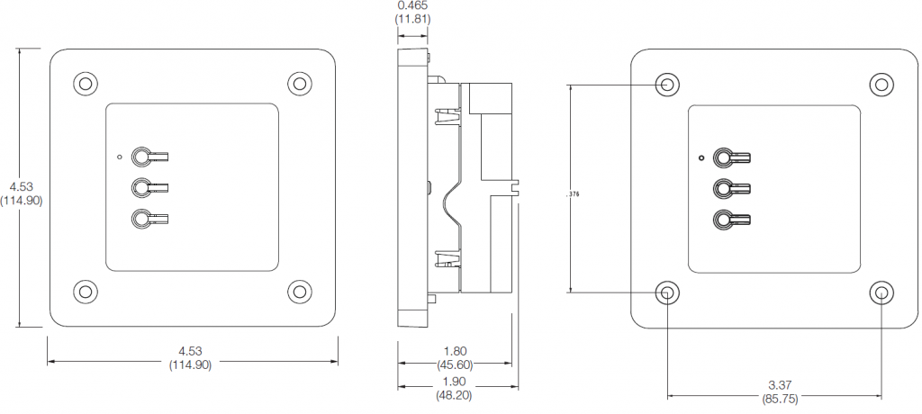
DimensionsDimensions are shown as: in (mm)
Range DiagramPowPak Module
Lutron, the Lutron logo, Clear Connect, Hi-lume, LED+, Pico, PowPak, Radio Powr Savr, RTISS Equipped, and Vive are trademarks or registered trademarks of Lutron Electronics Co., Inc. in the US and/or other countries. All other product names, logos, and brands are property of their respective owners.
![]()
References
[xyz-ips snippet=”download-snippet”]