
Wireless Occupancy Vacancy Ceiling SensorUser Manual
LRF -OCR2B-P-WH
LRF2-VCR2B-P-WH
 Models Available
 Models Available
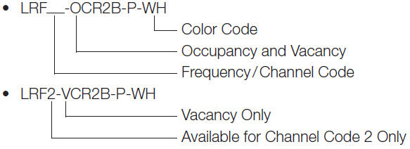
Frequency / Channel Codes
Available
2 = 431.0 – 437.0 MHz (U.S.A., Canada, Mexico, Brazil)3 = 868.125 – 869.850 MHz (Europe, U.A.E.)4 = 868.125 – 868.4755 MHz (China, Singapore)5 = 865.5 – 866.5 MHz (India)6 = 312.3 – 314.8 MHz (Japan)7 = 433.05 – 434.79 MHz (Hong Kong, Macau)
Color Code
WH = White
Compatible RF Devices
- For use with Lutron products only
- Supports simultaneous association with multiple Lutron Clear Connect devices and / or systems*
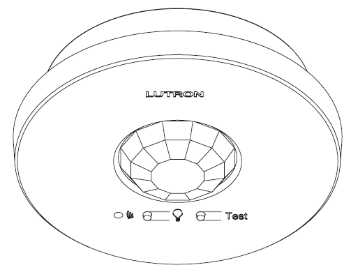
Radio Powr Savr Wireless Occupancy / Vacancy Ceiling Sensor
Lutron Radio Powr Savr occupancy / vacancy sensors are wireless, battery-powered, passive infrared (PIR) sensors that automatically control lights via RF communication to compatible dimming and switching devices. These sensors detect the heat (IR radiation of 9.5 μm) from people moving within an area to determine when the space is occupied. The sensors then wirelessly transmit the appropriate commands to the associated dimming and switching devices to turn the lights on or off automatically. They combine both convenience and exceptional energy savings potential along with ease of installation.
Features
- Wireless occupancy sensor has 3 settings available: Auto‑On / Auto-Off, Auto-On Low-Light / Auto-Off, and Manual-On / Auto-Off
- Auto-On Low-Light feature will turn lights on automatically only if there is less than approximately 10 Lux (1 fc) of ambient light
- Vacancy-only model available to meet California (U.S.A.) Title 24 requirements
- Uses Clear Connect technology
- Passive infrared motion detection with exclusive Lutron XCT Technology for fine motion detection
- 360˚ coverage ranges from 324 ft2 (30.2 m2) to 676 ft2 (62.4 m2), depending on mounting height
- Simple and intuitive adjustments available for Timeout, Auto-On, and Activity settings
- Supports advanced occupancy features, such as dependent occupancy groups and customizable occupied / unoccupied presets in some systems
- Multiple sensors can be added for extended coverage.Refer to product specification submittal of receiving device to determine system limits
- Lens illuminates during test mode to verify ideal locations
- Multiple ceiling-mount methods available for different ceiling materials
- Front accessible test buttons make programming easy
- 10-year battery life design
- RoHS compliant
Specifications
Regulatory
- Lutron Quality Systems Registered to ISO 9001:2008
Regulatory ApprovalsLRF2- (USA and Canada)
- cULus Listed
- FCC certified
- IC certified
- Meets CA (U.S.A.) Energy Commission Title 24 requirements
- COFETEL certified
- ANATEL certified
- SUTEL certified
LRF3-
- CE marked (European Union)
- TRA type approval (United Arab Emirates)
- CITC type approval (Saudi Arabia)
LRF4-
- SRRC type approval (Mainland China)
- iDA registered (Singapore)
LRF5-
- WPC Type (India)
LRF6-
- 007YUUL0689
LRF7-
- FCC
Power / Performance
- Operating voltage: 3 V-
- Operating current: 14 μA nominal
- Requires one CR 123 lithium battery
- 10-year battery life
- Non-volatile memory (saved changes are stored during power loss)
Environment
- Temperature: 32 ˚F to 104 ˚F (0 ˚C to 40 ˚C)
- For indoor use only
- Relative humidity: less than 90% non-condensing Warranty
- 5-Year Limited Warranty. For additional Warranty information, please visit www.lutron.com/ TechnicalDocumentLibrary/Sensor_Warranty.pdf
RF Range
LRF2-, LRF3-, LRF4-, LRF5-, LRF7-Local load controls must be located within 60 ft (18 m)line-of-sight, or 30 ft (9 m) through walls, of a sensor.
LRF6-
Local load controls must be located within 40 ft (12.2 m) line-of-sight, or 23 ft (7 m) through walls, of a sensor.Sensor Coverage Test
- Front accessible test button
- Lens illuminates orange in response to motion during test mode and is visible from 60 ft (18 m)
Wireless Communication Test
- Front accessible test button
- Turn associated loads on and off
Timeout Options
- 1 minute*
- 5 minutes
- 15 minutes (default setting)
- 30 minutes
Auto-On Options (Occupancy Versions Only)
- Enabled: Sensor turns lights ON and OFF automatically (default setting).
- Low Light: Sensor turns lights ON automatically only in low ambient light conditions; sensor turns lights OFF automatically.
- Disabled**: Lights must be turned ON manually from dimming or switching device; sensor turns lights OFF automatically.
Activity Options
- Low Activity: (default setting)
- Medium Activity:
- High Activity:
* Intended for use in high-activity, briefly occupied areas only.** During the 15-second grace period that begins when the lights are automatically turned off, the lights will automatically turn back on in response to motion. This grace period is provided as a safety and convenience feature in the event the lights turn off while the room is still occupied, so that the user does not need to manually turn the lights back on. After 15 seconds, the grace period expires and the lights must be manually turned on.
Installation Overview
Sensor Setup
- Sensor setup is available as a service by Lutron. For more information see the Sensor Layout and Tuning service document (Lutron P/N 3601235).
Sensor Placement
- To detect motion, the sensor requires line-of-sight of room occupants. The sensor must have an unobstructed view of the room. DO NOT mount behind or near tall cabinets, shelves, hanging fixtures, ceiling fans, etc. The sensor cannot see through glass objects such as patio- or shower doors.
- Hot objects and moving air currents can affect the performance of the sensor. To ensure proper operation, the sensor should be mounted at least 4 ft (1.2 m) away from HVAC vents and halogen or incandescent bulbs that are below the ceiling line.
- The performance of the sensor depends on a temperature differential between the ambient room temperature and that of room occupants. Warmer rooms may reduce the ability of the sensor to detect occupants.
- Devices emitting Radio Frequency (RF) energy can affect the performance of sensors. To ensure proper operation, sensors should be mounted at least 4 ft (1.2 m) away from devices that emit radio waves (e.g., microwave ovens, wireless routers, or other non-Clear Connect wireless devices). When using Clear Connect – Type X lamps or fixtures, ensure sensor is mounted at a distance of 2 ft (0.6 m) or greater from the lamp or fixture.
- For additional information on placing sensors, please see the Occupancy / Vacancy Sensor Design and Application Guide (P/N 368-3197) located at www.lutron.com
Mounting
Temporary mounting is optional to test sensor coverage and wireless communication before permanently installing the sensor.
Drop Ceiling (Compressed Fiber Ceiling Tile)
The mounting wire is provided for both temporary and permanent mounting of the sensor to ceiling tiles. It is designed to allow temporary mounting, testing, and repositioning (if necessary) of the sensor without damaging a ceiling tile. Once the final position of the sensor has been chosen, the mounting wire should be twisted together to permanently secure the sensor in place.
Solid Ceiling (Drywall, Plaster, Concrete, or Wood)
- Temporary mounting: Ten (10) temporary mounting strips can be purchased in the kit, L-CMDPIRKIT, for temporarily mounting and testing the sensor.
- Permanent mounting: Screws and anchors (for drywall or plaster) provided to mount the sensor.
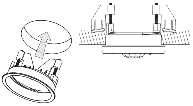
Recess-Mount
- Do not recess-mount sensor in a metal surface.
- Recess-mounting ring requires an opening of 3 in (76 mm) in diameter.
- Recess-mounting ring secures internally to ceiling. Sensor twists into the recess mounting ring and sits flush with ceiling (see image below).
- Recess-mounting ring purchased as a separate kit: L-CRMK-WH.
Dimensions

Coverage Diagrams
Per NEMA WD7 test method
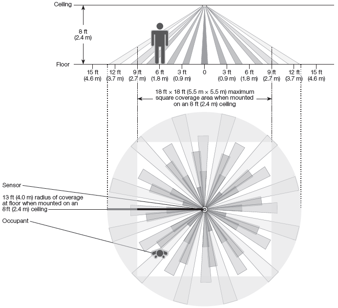
Sensor Coverage Chart (for sensor mounted in center of room)
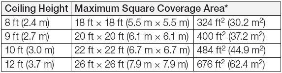
12 ft (3.7 m) is the recommended maximum mounting height
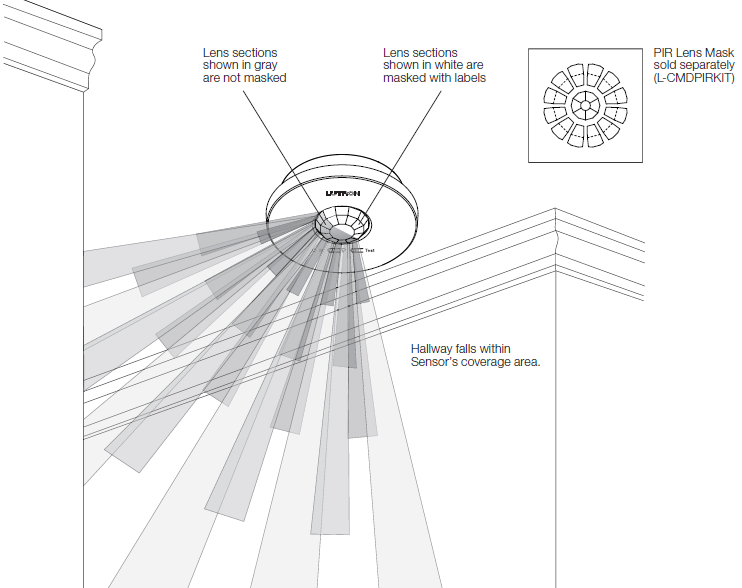
Lens Masking
Whenever possible, the sensor should be installed in a location where it cannot view areas outside the intended space, such as hallways or adjacent rooms. If this situation cannot be avoided, portions of the lens may be masked to block the view of the sensor into undesired areas. Ten (10) PIR Lens Masks may be purchased in the kit, L-CMDPIRKIT.
Lutron, Lutron, Clear Connect, Radio Powr Savr and XCT are trademarks or registered trademarks of Lutron Electronics Co., Inc. in the US and/or other countries.
References
[xyz-ips snippet=”download-snippet”]