![]()
MW325R 300Mbps Enhanced Wireless N Router
 REV2.0.0 1910080033
COPYRIGHT & TRADEMARK
Specifications are subject to change without notice. ![]() is a registered trademark of MERCUSYS TECHNOLOGIES CO., LTD. Other brands and product names are trademarks or registered trademarks of their respective holders.No part of the specifications may be reproduced in any form or by any means or used to make any rivative such as translation, transformation, or adaptation without permission from MERCUSYSTECHNOLOGIES CO., LIMITED. Copyright © 2017 MERCUSYS TECHNOLOGIES CO., LIMITED. All rights reserved.http://www.mercusys.com
is a registered trademark of MERCUSYS TECHNOLOGIES CO., LTD. Other brands and product names are trademarks or registered trademarks of their respective holders.No part of the specifications may be reproduced in any form or by any means or used to make any rivative such as translation, transformation, or adaptation without permission from MERCUSYSTECHNOLOGIES CO., LIMITED. Copyright © 2017 MERCUSYS TECHNOLOGIES CO., LIMITED. All rights reserved.http://www.mercusys.com
CE Mark Warning
![]()
This is a class B product. In a domestic environment, this product may cause radio interference, in which case the user may be required to take adequate measures.RF Exposure InformationThis device meets the EU requirements (2014/53/EU Article 3.1a) on the limitation of exposure of the general public to electromagnetic fields by way of health protection.
The device complies with RF specifications when the device is used at 20 cm from your body.
Safety Information
- When a product has a power button, the power button is one of the ways to shut off the product;when there is no power button, the only way to completely shut off power is to disconnect the product or the power adapter from the power source.
- Don’t disassemble the product, or make repairs yourself. You run the risk of electric shock and voiding the limited warranty. If you need service, please contact us.
- Avoid water and wet locations.
- The adapter shall be installed near the equipment and shall be easily accessible.
- The plug is considered as a disconnect device of the adapter.
 Use only power supplies which are provided by the manufacturer and in the original packing of this product.
Explanation of the symbols on the product label
| Symbol | Explanation |
| DC voltage | |
 |
RECYCLINGThis product bears the selective sorting symbol for Waste electrical and electronicequipment (WEEE). This means that this product must be handled pursuant toEuropean directive 2012/19/EU in order to be recycled or dismantled to minimize its impact on the environment.User has the choice to give his product to a competent recycling organization or tothe retailer when he buys a new electrical or electronic equipment. |
![]() MERCUSYS TECHNOLOGIES CO., LTD.DECLARATION OF CONFORMITYFor the following equipment:Product Description: 300Mbps Enhanced Wireless N RouterModel No.: MW325RTrademark: MERCURYWe declare under our own responsibility that the above products satisfy all the technical regulations applicable to the product within the scope of Council Directives:Directive 1999/5/EC, Directive 2014/30/EU, Directive 2014/35/EU, Directive 2011/65/EU,Directive 2009/125/ECThe above product is in conformity with the following standards or other normative documents:EN 300328 V1.9.1EN 301489-1 V1.9.2 & EN 301489-17 V2.2.1EN 55022: 2010+AC: 2011EN 55024: 2010EN 60950-1: 2006 + A11: 2009 + A1: 2010 + A12: 2011 +A2: 2013EN 50385: 2002EN 50581: 2012(EC) No 278/2009(EC) No 1275/2008(EU) No 801/2013The product carries the CE Mark:
MERCUSYS TECHNOLOGIES CO., LTD.DECLARATION OF CONFORMITYFor the following equipment:Product Description: 300Mbps Enhanced Wireless N RouterModel No.: MW325RTrademark: MERCURYWe declare under our own responsibility that the above products satisfy all the technical regulations applicable to the product within the scope of Council Directives:Directive 1999/5/EC, Directive 2014/30/EU, Directive 2014/35/EU, Directive 2011/65/EU,Directive 2009/125/ECThe above product is in conformity with the following standards or other normative documents:EN 300328 V1.9.1EN 301489-1 V1.9.2 & EN 301489-17 V2.2.1EN 55022: 2010+AC: 2011EN 55024: 2010EN 60950-1: 2006 + A11: 2009 + A1: 2010 + A12: 2011 +A2: 2013EN 50385: 2002EN 50581: 2012(EC) No 278/2009(EC) No 1275/2008(EU) No 801/2013The product carries the CE Mark:
![]()
The person responsible for marking this declaration:

Huang JingRegulatory Compliance Manager
Date of issue: 2017.04.20
MW325R 300Mbps Enhanced Wireless N Router User Guide
Conventions
The router or MW325R, or device mentioned in this User Guide stands for MW325R 300Mbps Enhanced Wireless N Router without any explanations.Parameters provided in the pictures are just references for setting up the product, which may differ from the actual situation.You can set the parameters according to your demand.*Maximum wireless signal rates are the physical rates derived from IEEE Standard 802.11 specifications. Actual wireless data throughput and wireless coverage are not guaranteed and will vary as a result of network conditions, client limitations, and environmental factors, includingbuilding materials, obstacles, volume and density of traffic, and client location.
More InfoSpecifications and the latest software can be found at the product page at the official websitehttp://www.mercusys.com.The Quick Installation Guide can be found where you find this guide or inside the package of the modem router.
Chapter 1. Introduction
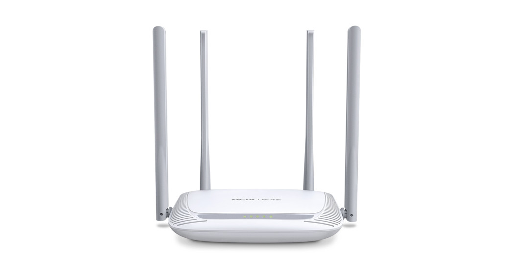
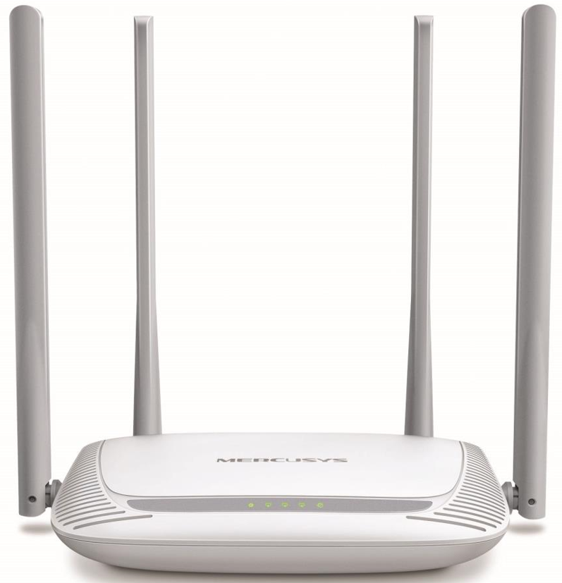
1.1 Product OverviewThe router integrates a 4-port Switch, Firewall, NAT-Router, and Wireless AP. Powered by 2×2 MIMO technology, the router delivers exceptional range and speed, which can fully meet the need of Small Office/Home Office (SOHO) networks and the users demanding higher networkingperformance.1.2 Product Appearance1.2.1 The Front Panel
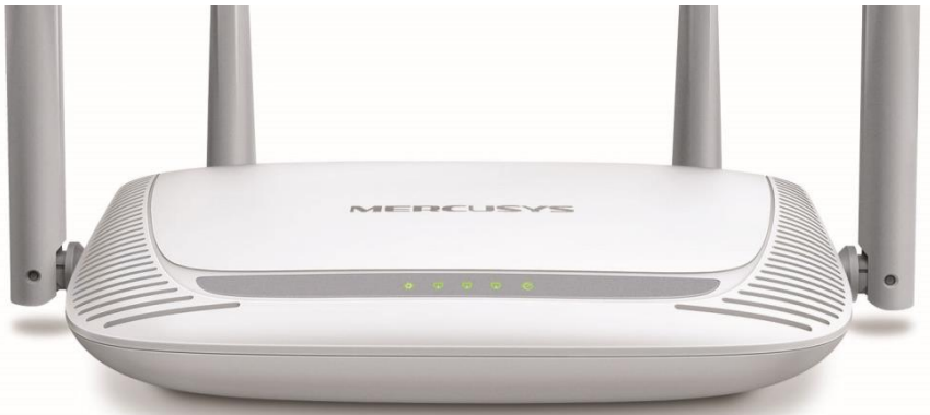
The router’s LEDs are located on the front panel (View from left to right).
| Name | Status | Indication |
| Off | The power is off. | |
| On | The power is on. | |
| Off | The corresponding port is not connected. | |
| On | The corresponding port is connected. | |
| Flashing | The corresponding port is transmitting/receiving data. | |
| Off | The WAN port is not connected. | |
| On | The WAN port is connected. | |
| Flashing | The WAN port is transmitting/receiving data. |
1.2.2 The Rear Panel
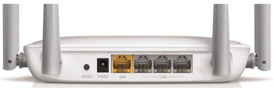
The following ports are located on the rear panel (View from left to right).
|
Port |
Description |
| RESET | Press and hold this button for more than 5 seconds to reset the router. |
| POWER | The power socket is where you will connect the power adapter. Please use the power adapter provided with this router. |
| WAN | This port is where you will connect the DSL/cable Modem, or Ethernet. |
| LAN | These ports connect the router to the local PC(s). |
| Wireless antenna | To receive and transmit the wireless data. |
Chapter 2. Connecting the Router
2.1 System Requirements
- Broadband Internet Access Service (DSL/Cable/Ethernet)
- One DSL/Cable Modem has an RJ45 connector (which is not necessary if the router is connected directly to the Ethernet.)
- PCs with a working Ethernet Adapter and an Ethernet cable with RJ45 connectors
- TCP/IP protocol on each PC
- Web browsers, such as Microsoft Internet Explorer, Mozilla Firefox or Apple Safari
2.2 Installation Environment Requirements
- Place the router in a well-ventilated place far from any heater or heating vent
- Avoid direct irradiation of any strong light (such as sunlight)
- Keep at least 2 inches (5 cm) of clear space around the router
- Operating Temperature: 0℃~40℃ (32℉~104℉)
- Operating Humidity: 10%~90%RH, Non-condensing
2.3 Connecting the RouterIf your Internet connection is through an Ethernet cable from the wall instead of through a DSL/Cable/Satellite modem, connect the Ethernet cable directly to the router’s Internet port, then follow steps 4 and 5 to complete the hardware connection.
- Turn off the modem and remove the backup battery if it has one.
- Connect the modem to the Internet port on your router with an Ethernet cable.
- Turn on the modem, and then wait about 2 minutes for it to restart.
- Turn on the router.
- Verify that the hardware connection is correct by checking these LEDs.
Power OnWAN On/Flashing
Chapter 3. Quick Installation Guide
This chapter will show you how to configure the basic functions of your router using Quick Setup Wizard within minutes.
NOTE:Before configuring the router, you need to set up the TCP/IP Protocol in Obtain an IP address automatically mode on your PC. For detailed instructions, please refer to Appendix B: Configuring the PC.
- To access the web management page, open a web-browser and enter the default domainname http://mwlogin.net in the address field.
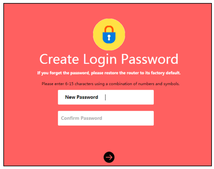
- A login window will appear. Create a login password when prompted. Then click For subsequent login, use the password you have set.
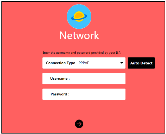
- Select your Internet connection type and enter the corresponding parameters with theinformation provided by your ISP and click. If you are not sure of the connection type, click Auto Detect. Here we use PPPoE as an example.
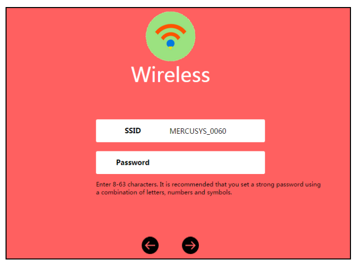
- Customize the SSID (network name) and password or leave them as default. It is recommended that you set a strong password using a combination of letters, numbers and symbols. Then click
- Click to complete the Quick Setup.
Chapter 4. Basic Configuration
After your successful login, you will see the basic configuration page. The main menus are on the left of the page. On the right you can configure the corresponding function.

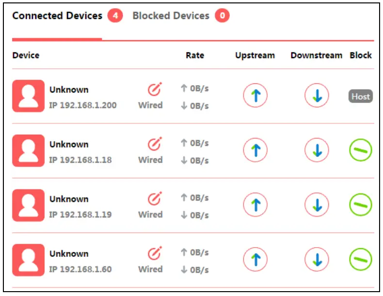
There are three functions on the Basic page: Device Management, Network and Wireless. Thedetailed explanations for each function are listed below.4.1 Device ManagementChoose Device Management, you can view and manage the connected or blocked devices on the page.
- Connected Devices• Device – Displays the name and IP address of the device. You can click to edit the device name.• Rate – Displays the current upstream and downstream speed of the device.• Upstream/Downstream – You can click the button in the column to set the upstream or downstream speed for the device.• Block – Click to remove the device from the list.
- Blocked Devices• Device – Displays the name and MAC address of the blocked device. You can clickto edit the device name.• Allow – Clickto remove the device from the list.
 • Device – Displays the name and IP address of the device. You can click
 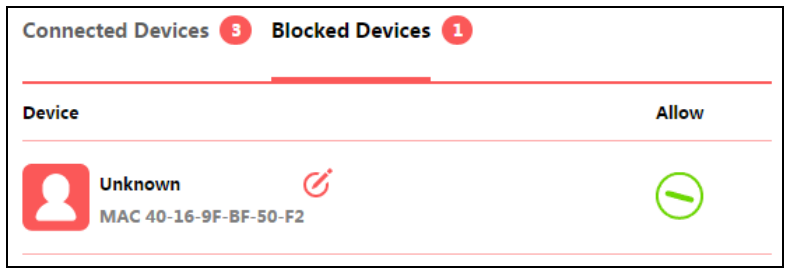 • Device – Displays the name and MAC address of the blocked device. You can click
4.2 NetworkChoose Network, you can view and customize the basic Internet settings on the page.
- PPPoEIf your ISP provides a PPPoE connection, select PPPoE, and enter the parameters.• Username/Password – Enter the username and password provided by your ISP. These fields are case-sensitive.
- Static IPIf your ISP provides a static IP Address, Subnet Mask, Gateway and DNS setting, select Static IP and enter the parameters.•IP Address – Enter the IP address in dotted-decimal notation provided by your ISP.• Subnet Mask – Enter the subnet Mask in dotted-decimal notation provided by your ISP, usually is 255.255.255.0.• Gateway – Enter the gateway IP address in dotted-decimal notation provided by your ISP.• Primary/Secondary DNS – Enter one or two DNS addresses in dotted-decimal notation provided by your ISP.Click Save to make the settings effective.
- Dynamic IPIf your ISP provides the DHCP service, select Dynamic IP, and the router will automatically get IP parameters from your ISP.4.3 WirelessChoose Wireless, and you can change the SSID (network name) and password on the page.• SSID (Wireless Network Name) – Enter a value of up to 32 characters. The default SSID is MERCUSYS_XXXX (XXXX indicates the last unique four numbers of each router’s MAC address). This field is case-sensitive.• Password – Enter 8-63 characters using a combination of numbers, letters and symbols. The security version is WPA2-PSK/WPA-PSK, which supports AES encryption that provides a good level of security. If you select No Security, the filed will be left blank.Click Save to make the settings effective.
 • Username/Password – Enter the username and password provided by your ISP. These fields are case-sensitive.
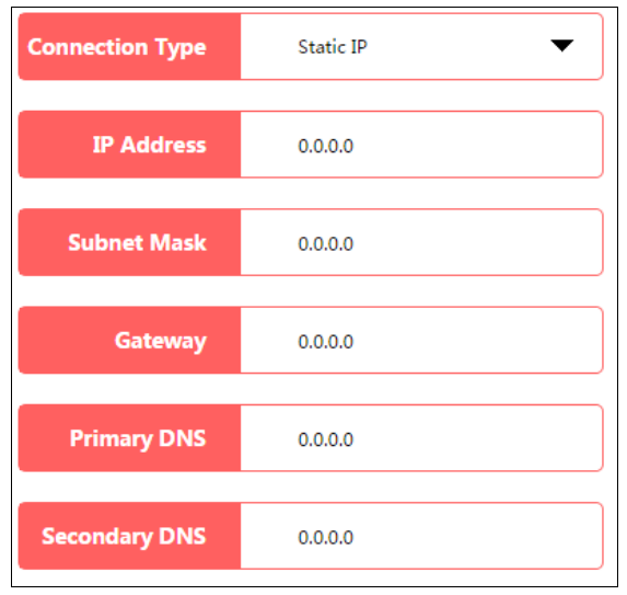 •IP Address – Enter the IP address in dotted-decimal notation provided by your ISP.• Subnet Mask – Enter the subnet Mask in dotted-decimal notation provided by your ISP, usually is 255.255.255.0.• Gateway – Enter the gateway IP address in dotted-decimal notation provided by your ISP.• Primary/Secondary DNS – Enter one or two DNS addresses in dotted-decimal notation provided by your ISP.Click Save to make the settings effective.
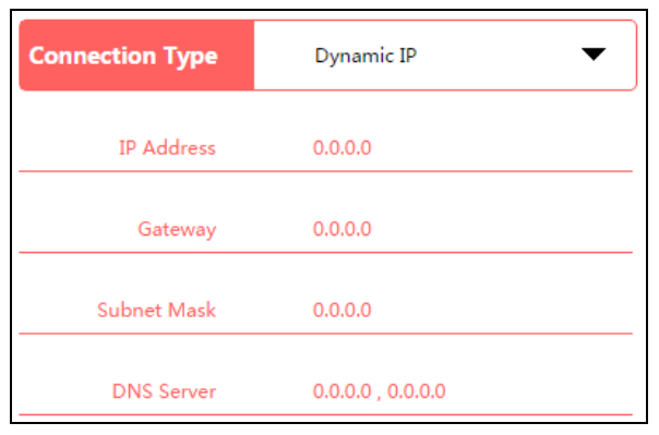 4.3 WirelessChoose Wireless, and you can change the SSID (network name) and password on the page.
Chapter 5. Advanced Configuration
This chapter will show each web page’s key functions and the configuration way.5.1 Network
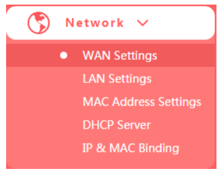
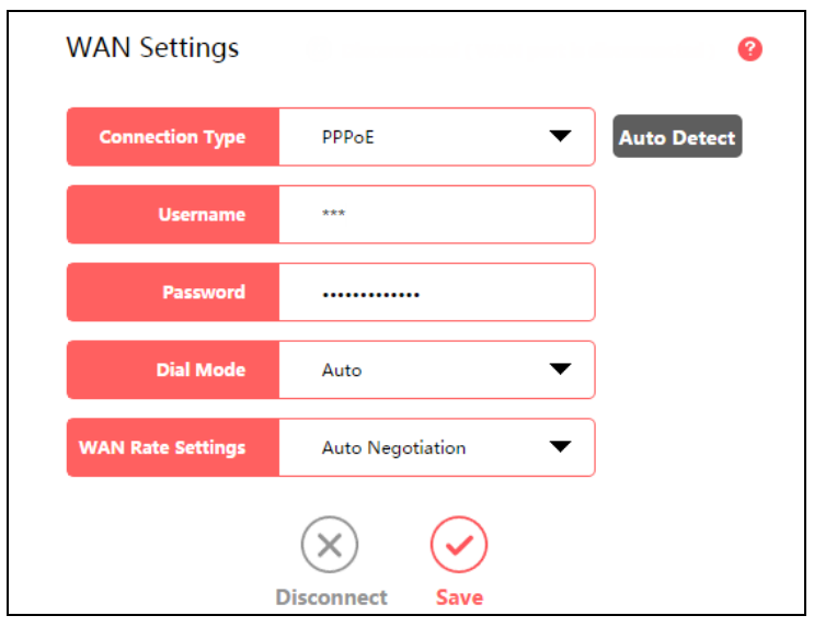
There are five submenus under the Network menu: WAN Settings, LAN Settings, MAC AddressSettings, DHCP Server and IP&MAC Binding. Click any of them, and you can configure the corresponding function.5.1.1 WAN SettingsGo to Network→WAN, you can configure the IP parameters of the WAN.1. If your ISP provides a PPPoE connection, select PPPoE, and enter the parameters.
- WAN Settings
- Username/Password – Enter the username and password provided by your ISP. These fields are case-sensitive.
- Dial Mode – Select the Dial Mode from the drop-down list. It is recommended that you keep the default Auto mode.
- WAN Rate Settings – You can select the rate and duplex mode for the WAN port. By default, it is Auto Negotiation.Click Save to make your settings effective.
- Connection Type
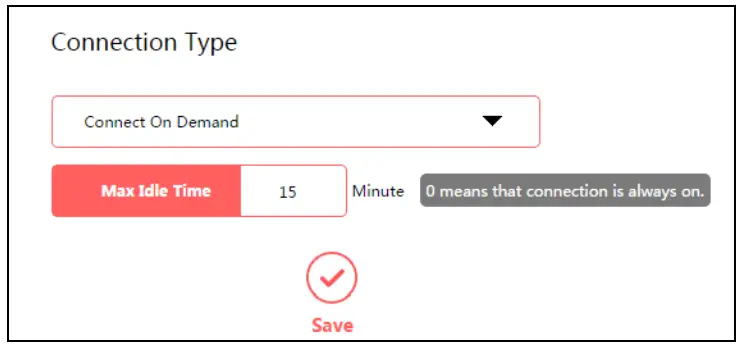
- Connect on Demand – In this mode, the Internet connection can be terminated automatically after a specified inactivity period (Max Idle Time) and be re-established when you attempt toaccess the Internet again. If you want your Internet connection keeps active all the time,please enter 0 in the Max Idle Time field. Otherwise, enter the number of minutes you want to have elapsed before your Internet access disconnects.
- Connect Automatically – The connection can be re-established automatically when it isdown.
- Connect Manually – This mode also supports the Max Idle Time function as Connect on Demand mode. The Internet connection can be disconnected automatically after a specified inactivity period.
Click Save to make the settings effective.
- PPPoE Advanced settings
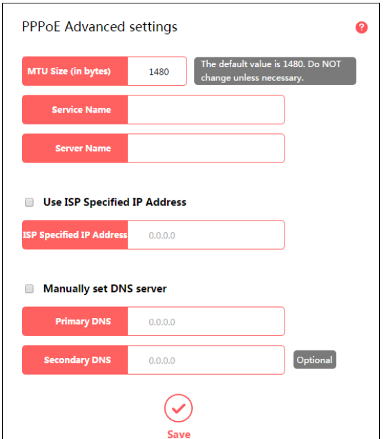
- MTU Size – The default MTU size is 1480 bytes. It is NOT recommended that you change the default MTU Size unless required by your ISP.
- Service Name/Server Name – The service name and server name should not be configured unless it is necessary for your ISP. In most cases, leaving these fields blank will work.
- ISP Specified IP Address – If your ISP does not automatically assign IP addresses to the router during login, please select Use ISP Specified IP Address and enter the IP address provided by your ISP in dotted-decimal notation.
- Primary DNS/Secondary DNS – If your ISP does not automatically assign DNS addresses to the router during login, please select Manually set DNS server and enter the IP address in dotted-decimal notation of your ISP’s primary DNS server. If a secondary DNS server address is available, enter it as well.
Click Save to make the settings effective.
2. If your ISP provides the DHCP service, select Dynamic IP, and the router will automatically get IP parameters from your ISP.
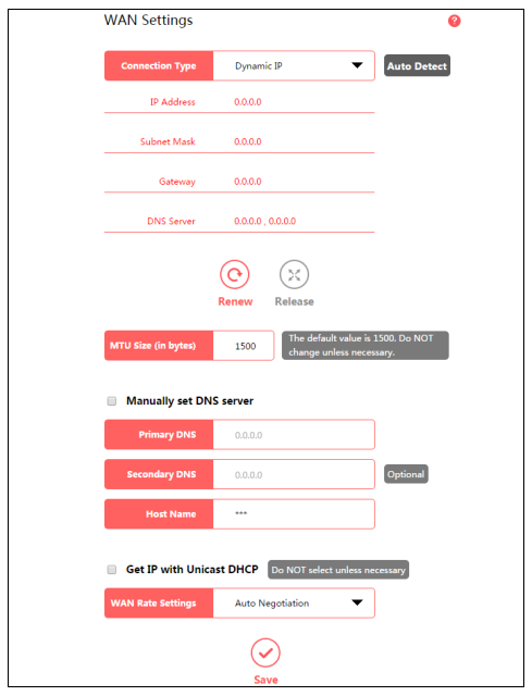
- Renew – Click to renew the IP parameters from your ISP.
- Release – Click to release the IP parameters.
- MTU Size – The normal MTU (Maximum Transmission Unit) value for most Ethernet networks is 1500 bytes. Do not change the default MTU Size unless required by your ISP.
- Manually set DNS server – If your ISP gives you one or two DNS addresses, select this option and enter the primary and secondary addresses into the corresponding fields. Otherwise, the DNS servers will be assigned dynamically from your ISP.
- Host Name – This option specifies the host name of the router.
- Get IP with Unicast DHCP – A few ISPs’ DHCP servers do not support the broadcast applications. If you cannot get the IP Address normally, you can choose this option. (It is rarely required.)
Click Save to make the settings effective.
3. If your ISP provides a static IP Address, Subnet Mask, Gateway and DNS setting, selectStatic IP.
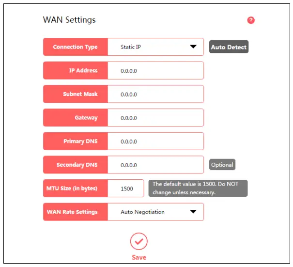
- IP Address – Enter the IP address in dotted-decimal notation provided by your ISP.
- Subnet Mask – Enter the subnet mask in dotted-decimal notation provided by your ISP, usually is 255.255.255.0.
- Gateway – Enter the gateway IP address in dotted-decimal notation provided by your ISP.
- MTU Size – The normal MTU (Maximum Transmission Unit) value for most Ethernet networks is 1500 Bytes. Do not change the default MTU Size unless required by your ISP.
- Primary/Secondary DNS – Enter one or two DNS addresses in dotted-decimal notation provided by your ISP.
Click Save to make the settings effective.
5.1.2 LAN SettingsGo to Network→LAN Settings, you can configure the IP parameters of the LAN on the screen as below.
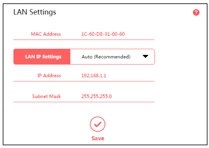
- MAC Address – The physical address of the router, as seen from the LAN. The value can’t be changed.
- LAN IP Settings – Select Auto or Manual. In Auto mode, the router will automatically detect the LAN-WAN IP address confliction.
- IP Address – Enter the IP address of your router.
- Subnet Mask – An address code that determines the size of the network. Normally use 255.255.255.0 as the subnet mask.
NOTE:
- If you change the LAN IP address, you must use the new IP address to log in to the router.
- If the new LAN IP address you set is not in the same subnet with the previous one, the IP Address pool in the DHCP server will be configured automatically, but the Virtual Server and DMZ Host will not take effect until they are re-configured.
5.1.3 MAC Address SettingsGo to Network→MAC Address Settings, you can configure the MAC address of the WAN on the page.
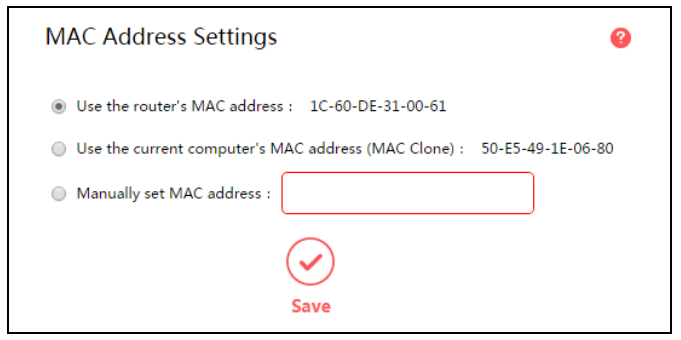
Some ISPs require that you register the MAC address of your adapter. Changes are rarely needed here.
- Use the router’s MAC address – By default, this option is selected.
- Use the current computer’s MAC address (MAC Clone) – Some ISPs will register the MAC address of your computer when you access the Internet for the first time through their Cable modem. If you add a router into your network to share your Internet connection, the ISP willnot accept it as the MAC address is changed. In this case, you need to clone your computer’s MAC address to the router.
- Manually set MAC address – If your ISP requires you to register the MAC address, please enter the correct MAC address into this field in XX-XX-XX-XX-XX-XX format (X is any hexadecimal digit).
Click Save to make the settings effective.
NOTE:Only the PC on your LAN can use the MAC Clone function.
5.1.4 DHCP ServerGo to Network→DHCP Server, you can configure the DHCP Server settings on the page. The router is set up by default as a DHCP (Dynamic Host Configuration Protocol) server, which provides the TCP/IP configuration for all the PCs that are connected to the router on the LAN.
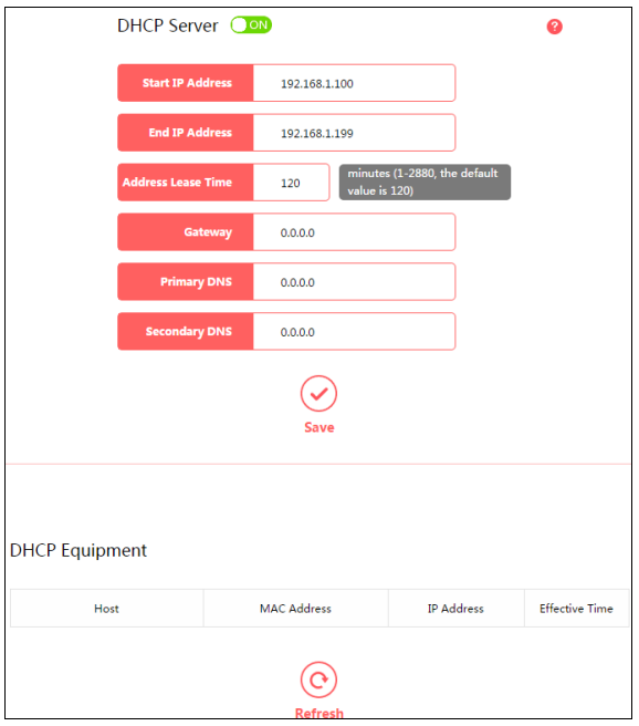
- DHCP Server – Click the button to enable or disable the DHCP server. If you disable the server, you must have another DHCP server within your network or else you must configure the computer manually.
- Start IP Address – Specify an IP address for the DHCP Server to start with when assigning IP addresses. 192.168.1.100 is the default start address.
- End IP Address – Specify an IP address for the DHCP Server to end with when assigning IP addresses. 192.168.1.199 is the default end address.
- Address Lease Time – The Address Lease Time is the amount of time a network user will be allowed connection to the router with their current dynamic IP Address. Enter the amount of time in minutes and the user will be leased this dynamic IP Address. After the time is up,the user will be automatically assigned a new dynamic IP address. The range of the time is 1 ~ 2880 minutes. The default value is 120 minutes.
- Gateway – (Optional.) It is recommended to enter the IP address of the LAN port of the router. The default value is 192.168.1.1.
- Primary DNS – (Optional.) Enter the DNS IP address provided by your ISP or consult your ISP.
- Secondary DNS – (Optional.) Enter the IP address of another DNS server if your ISP provides two DNS servers.
NOTE:To use the DHCP server function of the router, you must configure all computers on the LAN as Obtain an IP Address automatically.
- Host – The name of the DHCP client.
- MAC Address – The MAC address of the DHCP client
- IP Address – The IP address that the router has allocated to the DHCP client
- Effective Time – The time of the DHCP client leased. After the dynamic IP address has expired, a new dynamic IP address will be automatically assigned to the user.
Click Refresh to show the current attached devices.
5.1.5 IP & MAC BindingGo to Network→IP & MAC Binding, you can control access of a specific computer in the LAN by binding the IP address and the MAC address of the device together.
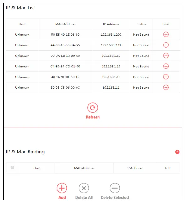
- Host – The name of the controlled computer in the LAN.
- MAC Address – The MAC address of the controlled computer in the LAN.
- IP Address – The assigned IP address of the controlled computer in the LAN.
- Status – Displays whether the MAC and IP address are bound or not.
- Bind – Click to add an entry to the IP & Mac binding list.
Click Refresh to refresh all items.To add an IP & MAC Binding entry, follow the steps below.
- Click Add.
- Enter the Host name.
- Enter the MAC Address of the device.
- Enter the IP Address that you want to bind to the MAC address.
- Click Save.
To edit an existing entry, follow the steps below.
- Find the entry in the table.
- Clickin the Edit column.
- Enter the parameters as you desire, then click Save.
To delete existing entries, select the entries in the table, then click Delete Selected.To delete all entries, click Delete All.5.2 Wireless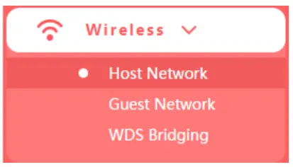 There are three submenus under the Wireless menu: Host Network, Guest Network and WDS Bridging. Click any of them, and you will be able to configure the corresponding function.
5.2.1 Host NetworkGo to Wireless→Host Network, you can configure the settings for the wireless host network on this page.
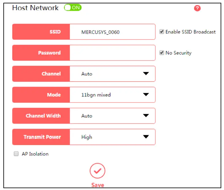
- SSID (Wireless Network Name) – Enter a value of up to 32 characters. The default SSID is MERCUSYS_XXXX (XXXX indicates the last unique four numbers of each router’s MAC address). This field is case-sensitive.
- Password – Enter 8-63 characters using a combination of numbers, letters and symbols. The security version is WPA2-PSK/WPA-PSK, which supports AES encryption that provides a good level of security. If you select No Security, the filed will be left blank.
- Channel – This field determines which operating frequency will be used. The default channel is set to Auto, so the router will choose the best channel automatically. It is not necessary to change the wireless channel unless you notice interference problems with another nearby access point.
NOTE:If 11bg mixed is selected in the Mode field, the Channel Width selecting field will turn grey andthe value will become 20M, which is unable to be changed.
- Mode – Select the desired mode.Select the desired wireless mode. It is strongly recommended to select 11bng mixed, and all of 802.11b, 802.11g and 802.11n wireless stations can connect to the router.11bgn mixed – Select if you are using a mix of 802.11b, 11g, and 11n wireless clients.11n only – Select if you are using only 11n wireless clients.11bg mixed – Select if you are using both 802.11b and 802.11g wireless clients.11g only – Select if you are using only 11g wireless clients.11b only – Select if you are using only 11b wireless clients.
- Channel width – Select the channel width from the drop-down list. The default setting is Auto, which can adjust the channel width for your clients automatically.
- Enable SSID Broadcast – If you select the Enable SSID Broadcast checkbox, the wireless router will broadcast its name (SSID) on the air.
- AP Isolation – Select this checkbox to enable the AP Isolation feature that allows you to confine and restrict all wireless devices on your network from interacting with each other, but still able to access the Internet. AP isolation is disabled by default.
5.2.2 Guest NetworkGo to Wireless→Guest Network, you can configure the settings for the wireless guest network on this page.

- Guest Network – Click to enable or disable the Guest Network function here.
- SSID/Password – Set the network name and password for Guest Network. Password may contain 8-63 characters. It is recommended you use a combination of numbers, letters and symbols.
- Access my local network – If Yes is selected, the wireless devices on the guest network are able to access your local network. The default value is No.
- Upstream Bandwidth – The upload speed through the WAN port for Guest Network.
- Downstream Bandwidth – The download speed through the WAN port for Guest Network.
- Set Guest Access Time – During this time the wireless stations could access the AP.
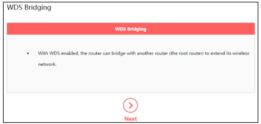
5.2.3 WDS Bridging
Go to Wireless→WDS Bridging, and follow the steps below to configure WDS bridging settings.
- Click Next to start the setup.
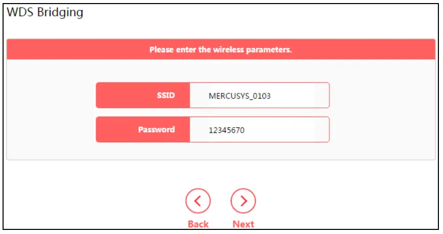
- Select a network from the table and enter the password, or you can click Add router manually and enter the network name and password. Then click Next.
- Enter the wireless parameters of your router. It is recommended to set the same SSID and Password as the root router. Then click Next.
- Check the parameters and click Finish to complete the setup.
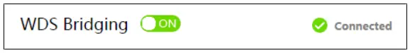
- The following information indicates successful connection.
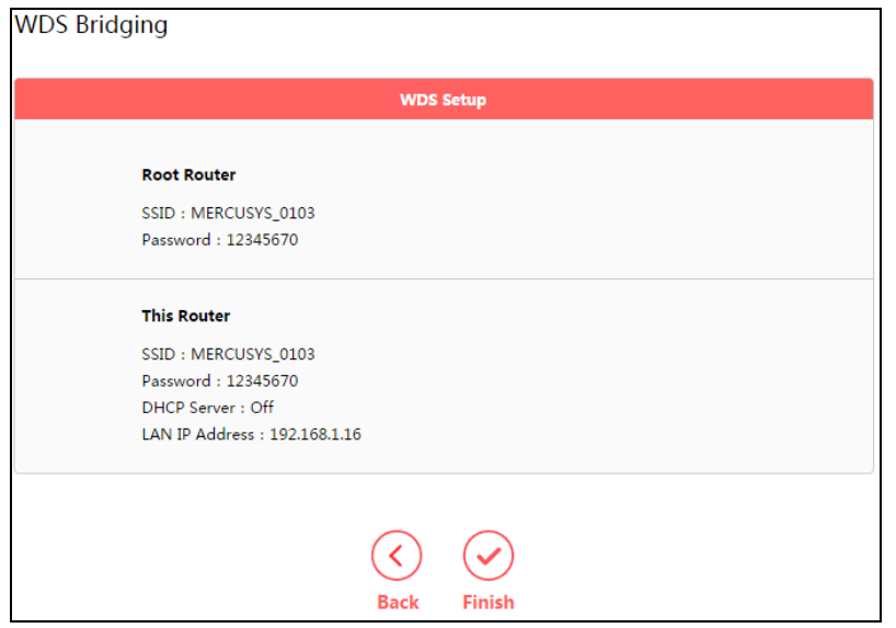
Note: If you have changed the LAN IP address of your router during the setup, you need to log in to the web management page using the domain name (mwlogin .net) or the new LAN IP you have just set.
5.3 Network Control
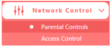
There are two submenus under the Network Control menu: Parental Controls and Access Control. Click any of them, and you will be able to configure the corresponding function.
5.3.1 Parental ControlsGo to Network Control→Parental Controls, and then you can configure the parental controls in the screen. The Parental Controls function can be used to control the internet activities of the child, limit the child to access certain websites and restrict the time of surfing.
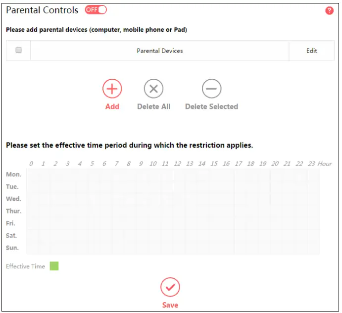
- Parental Controls – Click to enable or disable this function.
- Parental Devices – Displays the MAC address of the controlling PC.
- Edit – Here you can edit an existing entry.
- Add – Click to add a new device.
- Delete All – Click to delete all devices in the table.
- Delete Selected – Click to delete selected devices in the table.
- Effective Time – All devices except the parental devices will be restricted. Click and drag across the cells to set the restriction time periods.
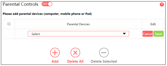
To add a new entry, follow the steps below.
- Click Add.
- Select a device from the drop-down list.
- Click Save.
To set the effective time, follow the steps below.
- Click and drag across the cells to set the restriction time periods.
- Click Save.
5.3.2 Access ControlGo to Network Control→Access Control, and then you can configure the access control in thescreen.
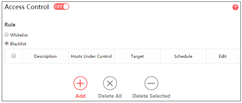
- Access Control – Click the button to enable or disable Access Control.
- White List – Select to allow only the Internet activities specified in the table.
- Black List – Select to block only the Internet activities specified in the table
- Description – Displays the name of the rule and this name is unique.
- Hosts Under Control – Displays the host selected in the corresponding rule.
- Target – Displays the target selected in the corresponding rule.
- Schedule – Displays the schedule selected in the corresponding rule.
- Edit – Here you can edit an existing rule.
- Add – Click to add a new rule entry.
- Delete All – Click to delete all the entries in the table.
- Delete Selected – Click to delete selected entries in the table.
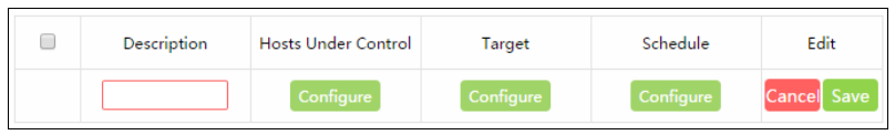
To add a new rule, follow the steps below.
- Toggle on to enable Access Control.
- Select Whitelist or Blacklist.
- Click Add and enter a brief description for the rule.
- Click Configure in the Hosts Under Control column to add a host, then click Apply.•Host Description – In this field, create a unique description for the host.•Mode – Here are two options, IP Address and MAC Address. You can select either of them from the drop-down list.If the IP Address is selected, you can see the following item:•IP Address Range – Enter the IP address or address range of the host in dotted-decimal format (e.g. 192.168.0.23).If the MAC Address is selected, you can see the following item:•MAC Address – Enter the MAC address of the host in XX-XX-XX-XX-XX-XX format (e.g. 00-11-22-33-44-AA).
- Click Configure in the Target column, you can select Any Target, or select Add to add a new target. Then click Apply.•Description – In this field, create a description for the target. Note that this description should be unique.• Mode – Here are two options, IP Address and Website Domain. You can choose either of them from the drop-down list.If the IP Address is selected, you will see the following items:•IP Address Range – Enter the IP address (or address range) of the target (targets) in dotted-decimal format.•Common Service – Here lists some common service ports. Select one from the drop-down list, and the corresponding port number will be filled in the Port field automatically. For example, if you select HTTP, 80 will be filled in the Port automatically.•Port – Specify the port or port range for the target. For some common service ports, you can make use of the Common Service item above.•Protocol – Here are three options, All, TCP and UDP. Select one of them from the drop-down list for the target.If the Website Domain is selected, you will see the following items:•Domain Name – Here you can enter 4 domain names, either the full name or the keywords (for example, Mercusys). Any domain name with keywords in it (www.mercusys.com) will be blocked or allowed.
- Click Configure in the Schedule column, you can select Any Time, or select Add to add a new schedule. Then click Apply.•Description – In this field, create a description for the schedule. Note that this description should be unique.•Time – Click and drag across the cells to set the effective time periods.
- Click Save to complete the settings.
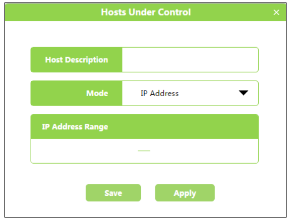 •Host Description – In this field, create a unique description for the host.•Mode – Here are two options, IP Address and MAC Address. You can select either of them from the drop-down list.If the IP Address is selected, you can see the following item:•IP Address Range – Enter the IP address or address range of the host in dotted-decimal format (e.g. 192.168.0.23).If the MAC Address is selected, you can see the following item:•MAC Address – Enter the MAC address of the host in XX-XX-XX-XX-XX-XX format (e.g. 00-11-22-33-44-AA).
 •Description – In this field, create a description for the target. Note that this description should be unique.• Mode – Here are two options, IP Address and Website Domain. You can choose either of them from the drop-down list.If the IP Address is selected, you will see the following items:•IP Address Range – Enter the IP address (or address range) of the target (targets) in dotted-decimal format.•Common Service – Here lists some common service ports. Select one from the drop-down list, and the corresponding port number will be filled in the Port field automatically. For example, if you select HTTP, 80 will be filled in the Port automatically.•Port – Specify the port or port range for the target. For some common service ports, you can make use of the Common Service item above.•Protocol – Here are three options, All, TCP and UDP. Select one of them from the drop-down list for the target.If the Website Domain is selected, you will see the following items:•Domain Name – Here you can enter 4 domain names, either the full name or the keywords (for example, Mercusys). Any domain name with keywords in it (
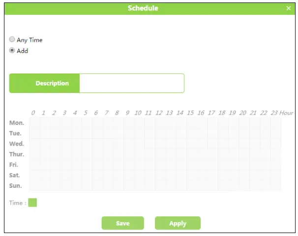 •Description – In this field, create a description for the schedule. Note that this description should be unique.•Time – Click and drag across the cells to set the effective time periods.
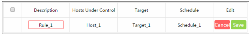
5.4 Advanced Users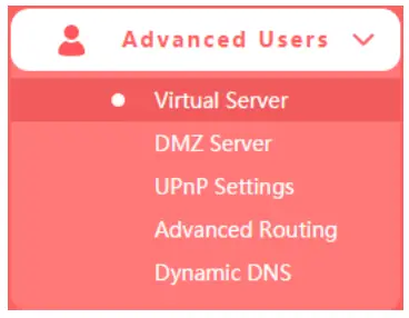
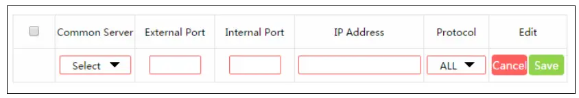
There are five submenus under the Forwarding menu: Virtual Server, DMZ Server, UPnPSettings, Advanced Routing and Dynamic DNS. Click any of them, and you will be able toconfigure the corresponding function.5.4.1 Virtual ServerGo to Advanced Users→Virtual Server, and then you can view and add virtual server on the page. Virtual server can be used for setting up public services on your LAN.
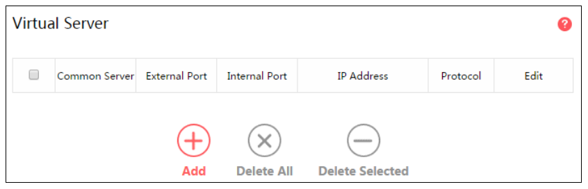
- Common Server – Some common services already exist in the drop-down list.
- External Port – The numbers of External Service Ports. You can enter a service port or range of service ports (the format is XXX – YYY; XXX is the Start port and YYY is the Eport).
- Internal Port – The Internal Service Port number of the PC running the service applicatiYou can leave it blank if the Internal Port is the same as the External Port, or enter specific port number when External Port is a single one.
- IP Address – The IP address of the PC running the service application.
- Protocol – The protocol used for this application, either All (all protocols supported by router), TCP or UDP.
- Edit – Here you can edit an existing entry.
- Add – Click to add a new rule entry.
- Delete All – Click to delete all the entries in the table.
- Delete Selected – Click to delete selected entries in the table.
To set up a virtual server entry:
- Click Add.
- Select a service from drop-down list to automatically populate the appropriate port number in the External Port field. If the service that you want to use is not listed, enter the number of the service port or service port range in the External Port field.
- Leave the Internal Port blank if it is the same as the External Port, or enter a specific port number if the External Port is a single port.
- Enter the IP address of the computer running the service application in the IP Address field.
- Select the protocol used for this application in the Protocol drop-down list, either TCP, UDP,or All (All protocols supported by the router).
- Click Save.
NOTE:Please make sure the external port is different from the port used for local and remote management, or the virtual server may not be working properly.
To modify an existing entry:
- Find the desired entry in the table.
- Click in the Edit column.
- Click Save to make the settings effective.
5.4.2 DMZ ServerGo to Advanced Users→DMZ Server, and then you can view and configure DMZ host on the page. The DMZ host feature allows one local host to be exposed to the Internet for a special-purpose service such as Internet gaming or video conferencing.
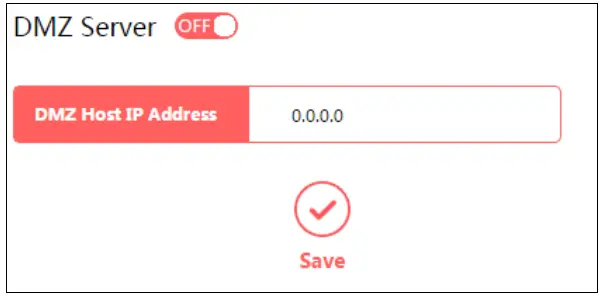
To assign a computer or server to be a DMZ server:
- Toggle On to enable DMZ Server.
- Enter the IP address of a local PC that is set to be DMZ host in the DMZ Host IP Address field.
- Click Save.
5.4.3 UPnP SettingsGo to Advanced Users→UPnP Settings, and then you can view the information about UPnP.The Universal Plug and Play (UPnP) feature allows the devices, such as Internet computers, to access the local host resources or devices as needed. UPnP devices can be automatically discovered by the UPnP service application on the LAN.
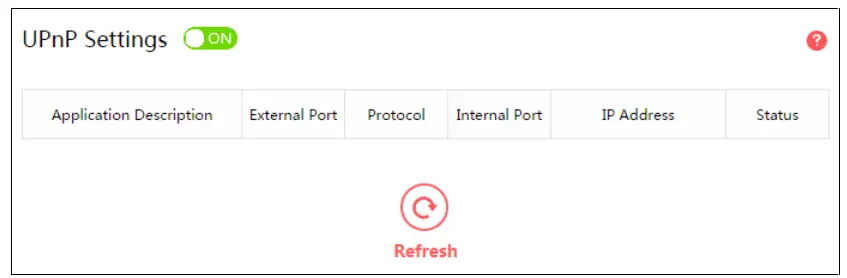
- Application Description – The description about the application which initiates the UPnP request.
- External Port – The port which the router opened for the application.
- Protocol – The type of protocol which is opened.
- Internal Port – The port which the router opened for local host.
- IP Address – The IP address of the local host which initiates the UPnP request.
- Status – Displays the port is active or not.
- Refresh – Click to update the current UPnP settings List.
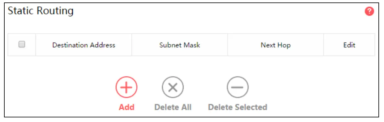
5.4.4 Advanced RoutingGo to Advanced Users→Advanced Routing, and then you can configure the static routing and view system routing list. Advanced routing is used to predetermine a fixed route for the network information packets to reach a specific host or network.
- Static Routing
- Destination Address – The address of the network or host that you want to assign to a static route.
- Subnet Mask – The Subnet Mask determines which portion of an IP Address is the network portion, and which portion is the host portion.
- Next Hop – The IP Address of the gateway device that allows for contact between the router and the network or host.
- Edit – Here you can edit an existing entry.
- Add – Click to add a new rule entry.
- Delete All – Click to delete all the entries in the table.
- Delete Selected – Click to delete selected entries in the table.
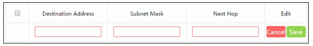
To add a static routing entry:
- Click Add.
- Enter the parameters in the corresponding fields.
- Click Save to make the settings effective.
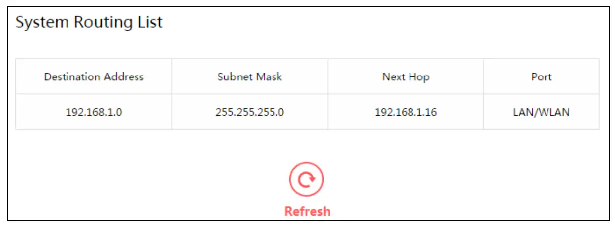
- System Routing List
- Destination Address – The address of the network or host to which the static route is assigned.
- Subnet Mask – The subnet mask determines which portion of an IP address is the network portion, and which portion is the host portion.
- Next Hop – The IP address of the gateway device that allows for contact between the router and the network or host.
- Port – Displays either the Destination IP Address is on the LAN/WLAN or on the WAN.
5.4.5 Dynamic DNSGo to Advanced Users→Dynamic DNS, and you can configure the Dynamic DNS function.
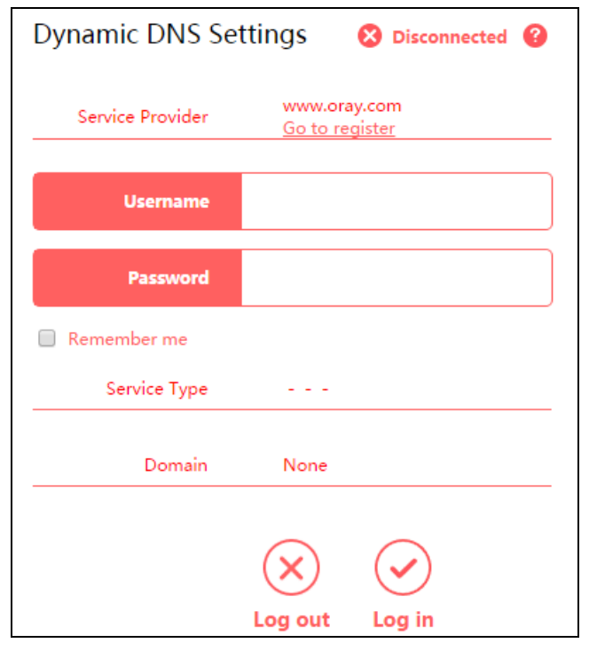
- Service Provider – The Dynamic DNS service provider.
- Username/Password – Enter the username and password of your DDNS account.
- Service Type – The current DDNS service type.
- Domain – Enter the domain name provided by the DDNS service provider.
To set up for Dynamic DNS, follow these steps:
- Enter the username and password for your DDNS account.If you do not have an account, click Go to register an account.
- Click Log in to log in to the DDNS service.
NOTE:If you want to log in again with another account after a successful login, please click Log out, then enter your new username and password and click Log in.
5.5 System Tools5.5.1 Web ManagementGo to System Tools→Web Management, and then you can configure the management rule on the page.

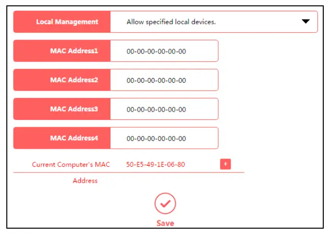
- Local Management
To allow specific devices to access and manage the router locally, follow these steps:
- Select Allow specified local devices.
- Enter each MAC address in a separate field. You can clickto add your PC’s MAC address to the list above.
- Click Save.
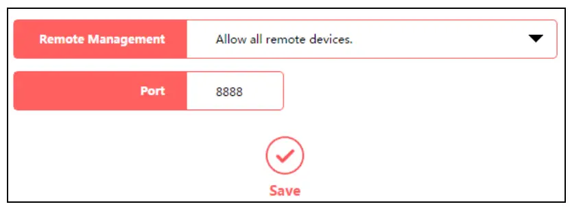
- Remote Management
To allow all devices to access and manage the router remotely, follow the steps below:
- Select Allow all remote devices.
- Enter the port number to be used to access the router between 1024 and 65535. The default value is 8888.
- Click Save.
To allow specified devices to access and manage the router remotely, follow the steps below:
- Select Allow specified remote devices.
- Enter the IP Address you will use when accessing your router from the Internet.3. Enter the port number to be used to access the router between 1024 and 65535. The default value is 8888.
- Click Save.
NOTE:
- To access the router, you should type your router’s WAN IP address into your browser’s address field, followed by a colon and the custom port number (e.g. http://202.96.12.8:8080). After entering the correct password, you will be able to access the router’s web management page.
- Be sure to set a very secure password for the router.
5.5.2 Time SettingsGo to System Tools→Time Settings, and then you can configure the time on the following page.
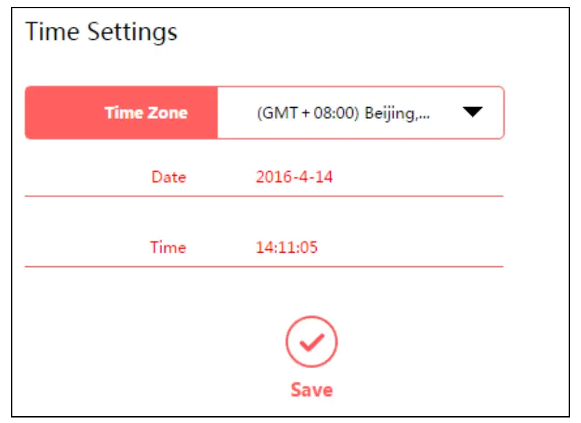
- Time Zone – Select your local time zone from this drop-down list.
- Date/Time – The router automatically obtains GMT from the Internet based on the time zone you select.
To change the time settings, follow these steps:
- Select your local time zone from the drop-down list.
- Click Save.NOTE:This setting will be used for some time-based functions such as Parental Controls and Access Control. Please specify your time zone before you configure these functions.
5.5.3 Firmware UpgradeGo to System Tools→Firmware Upgrade, and then you can update the latest version of firmware for the router on the page.
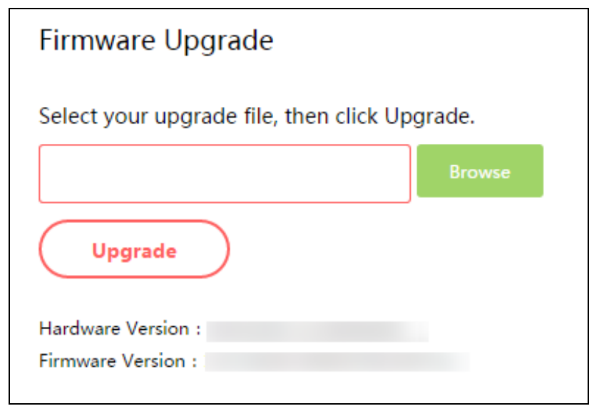
- Hardware Version – Displays the current hardware version. The version of the upgrade file must accord with the router’s current hardware version.
- Firmware Version – Displays the current firmware version.
To upgrade the router’s firmware, follow the steps below:
- Download the latest firmware upgrade file from our website (www.mercusys.com).
- Click Browse to locate and select the downloaded firmware file.
- Click Upgrade.
- The router will reboot automatically after the upgrade.
NOTE:To avoid any damage, it is important to keep the router powered on during the entire process.
5.5.4 Factory DefaultsGo to System Tools→Factory Default Restore, and then and you can restore the configurations of the router to factory defaults.
Click Restore to reset all configuration settings to their default values.
- The default IP address: 192.168.1.1
- The default Subnet Mask: 255.255.255.0
NOTE:All your custom settings will be lost when defaults are restored.
5.5.5 Backup & RestoreGo to System Tools→Backup & Restore, and then you can save the current configuration of the router as a backup file and restore the configuration via a backup.
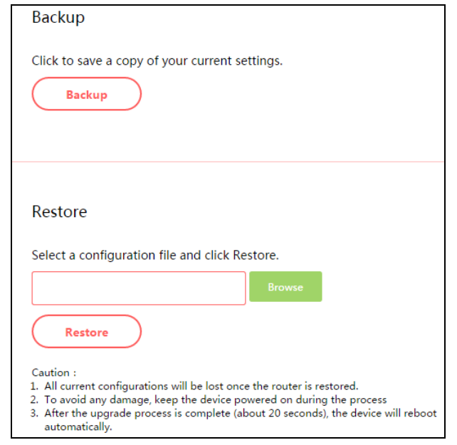
Click Backup to save all configuration settings as a backup file to your local computer.
To upgrade the router’s configuration, follow the steps below.
- Click Browse to locate and select the configuration file which you want to restore.
- Click Restore to update the configuration with the file you have selected.
NOTE:
- All current configurations will be lost once the router is restored.
- To avoid any damage, keep the device powered on during the process
- After the upgrade process is complete (about 20 seconds), the device will reboot automatically.
5.5.6 Reboot
Go to System Tools→Reboot, and then you can click the Reboot button to reboot the router on the page.
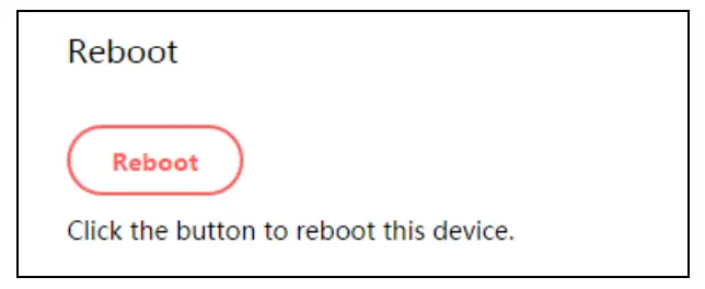
Some settings of the router will take effect only after rebooting, which include:
- Upgrade the firmware of the router (the system will reboot automatically).
- Restore the router’s settings to factory defaults (the system will reboot automatically).
- Update the configuration with the file (the system will reboot automatically).
5.5.7 Change Login PasswordGo to System Tools→Change Login Password, and then you can change the login username and password of the router on the page.

To change the router’s login password, follow the steps below.
- Enter the Old Password of the router.
- Enter the New Password.
- Enter the new password in the Confirm New Password field.
- Click Save.For subsequent logins, use the new password you have set.
5.5.8 Diagnostic Tools
Go to System Tools→Diagnostic Tools, and then you can test the Internet connection of your network via Ping or Tracert on the page.
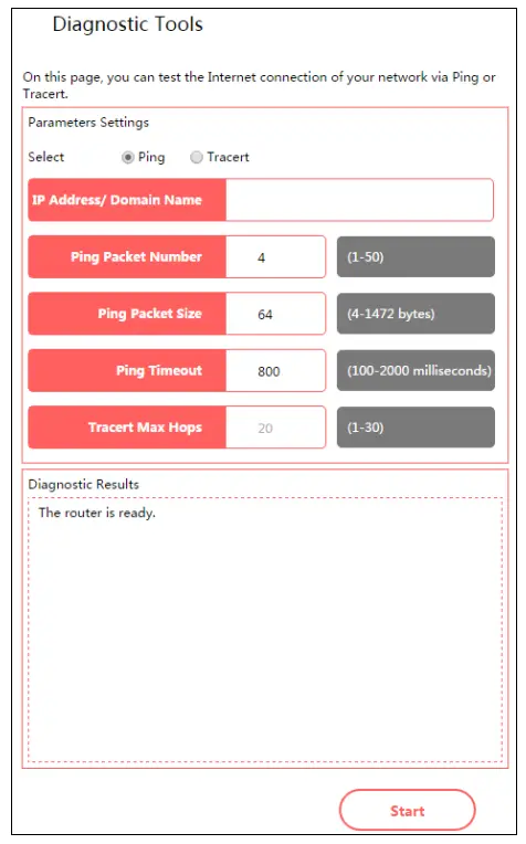
- Ping – This diagnostic tool troubleshoots connectivity, reachability, and name resolution to a given host or gateway.
- Tracert – This diagnostic tool tests the performance of a connection.
NOTE:You can use ping/tracert to test numeric IP addresses or domain names. If pinging/tracerting the IP address is successful, but pinging/tracerouting the domain name is not, you might have a name resolution problem. In this case, ensure that the specified domain name can be resolved by using Domain Name System (DNS) queries.
- IP Address/Domain Name – Enter the IP address or domain name of the PC whose connection you wish to diagnose.
- Pings Packet Number – Specifies the number of Echo Request messages sent. The default is 4.
- Ping Packet Size – Specifies the number of data bytes to be sent. The default is 64.
- Ping Timeout – Time to wait for a response, in milliseconds. The default is 800.
- Tracert Max Hops – Set the maximum number of hops (max TTL to be reached) in the path to search for the target (destination). The default is 20.Click Start to check the connectivity of the Internet.The Diagnostic Results page displays the result of the diagnosis.
NOTE:
- Only one user can use the diagnostic tools at one time.
- Ping Packet Number, Ping Packet Size, and Ping Timeout are Ping Parameters, and Tracert Max Hop is Tracert Parameter.
5.5.9 System LogGo to System Tools→System Log, and then you can view the logs of the router.
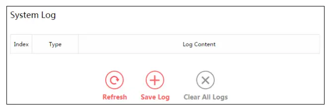
- Refresh – Refresh the page to show the latest log list.
- Save Log – Click to save all the logs in a text file.
- Clear All Logs – All the logs will be deleted from the router permanently, not just from the page.
Appendix A: Troubleshooting
T1. What can I do if I forget my password?
- For wireless password: By default, the wireless network has no password. If you have set a password for the network, log in to the router’s web management page, go toBasic→Wireless to obtain or reset your password.
- For the web management page password: Restore the router to its factory default settings and then create a new password when prompted.
T2. How do I restore my modem router’s configuration to its factory default settings?There are two ways to reset the modem router.Method one: With the router powered on, press and hold the RESET button for at least 5 seconds until all LEDs turn on momentarily. And then release the button and wait the router to reboot to its factory default settings.Method two: Restore the default setting from Advanced→System Tools→Factory DefaultRestore of the router’s web management page.NOTE:Once the modem router is reset, the current configuration settings will be lost and you will need to re-configure the router.
T3. What can I do if I cannot log in to the router’s web management page?This can happen for a variety of reasons, please try the methods below.
- Make sure the router connects to the computer correctly and the corresponding LED indicator(s) light up.
- Make sure the IP address of your computer is configured as Obtain an IP address automatically and Obtain DNS server address automatically.
- Make sure http://mwlogin.net is correctly entered.
- Check your computer’s settings:1) Go to Start→Control Panel→Network and Internet, and click View network status and tasks;2) Click Internet Options on the bottom left;3) Click Connections, and select Never dial a connection;
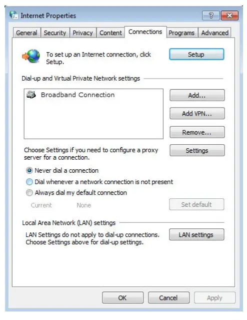
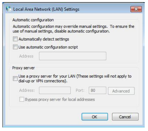
4) Click LAN settings, deselect the following three options and click OK;
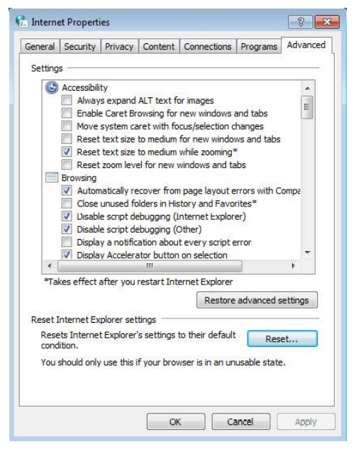
5) Go to Advanced→Restore advanced settings, and click OK to save the settings.
- Change a web browser or computer and log in again.
- Reset the modem router to factory default settings.Note: You’ll need to reconfigure the router to surf the Internet once the router is reset.
T4. What can I do if I cannot access the Internet?
- Make sure the router connects to the computer correctly and the corresponding LED indicator(s) light up.
- Check to see if you can log in to the web management page of the router. If you can, try the following steps. If you cannot, please set your computer by referring to T3 and then try to see if you can access the Internet. If the problem persists, please go to the next step.
- Make sure you have selected the proper WAN Connection Type and entered the parameters correctly.
- Go to Advanced→Network→MAC Address Settings to clone the MAC address.
- If you still cannot access the Internet, please restore your router to its factory default settings and reconfigure your modem router by following the instructions in Chapter 3 Quick Installation Guide.
- Please feel free to contact our Technical Support if the problem still exists.
Appendix B: Configuring the PCIn this section, we’ll introduce how to install and configure the TCP/IP correctly in Windows 7. First make sure your Ethernet Adapter is working, refer to the adapter’s manual if needed.
Install TCP/IP component
- On the Windows taskbar, click the Start button, and then click Control Panel.
- Click the Network and Internet, and click the Network and SharinCenter, then click Change adapter settings.
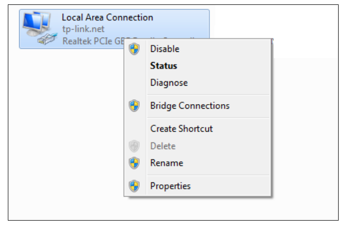
- Right, click the icon that showed below, select Properties on the prompt page.
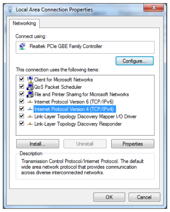
- In the prompt page that showed below, double click on the Internet Protocol Version 4 (TCP/IPv4).
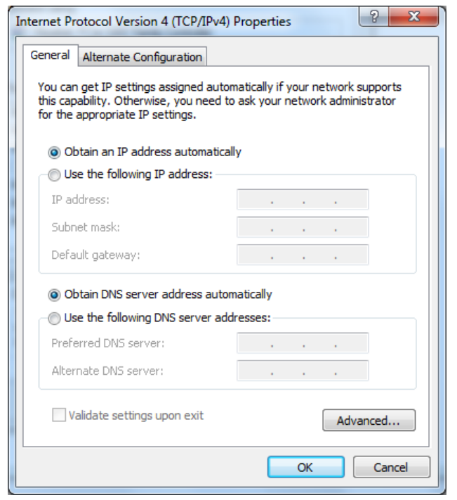
- The following TCP/IP Properties window will display and the IP Address tab is open on this window by default.
Now you have two ways to configure the TCP/IP protocol below:
- Setting IP address automaticallySelect Obtain an IP address automatically, Choose Obtain DNS server automatically, as shown in the Figure below:
• Setting IP address manually
- Select Use the following IP address radio button. And the following items are available
- If the router’s LAN IP address is 192.168.1.1, specify the IP address as 192.168.1.x (x is from to 254), and Subnet mask is 255.255.255.0.
- Enter the router’s LAN IP address (the default IP is 192.168.1.1) in the Default gateway field.
- Select Use the following DNS server addresses radio button. In the Preferred DNS Server field, you can type the DNS server IP address, which has been provided by your ISP
 report this ad
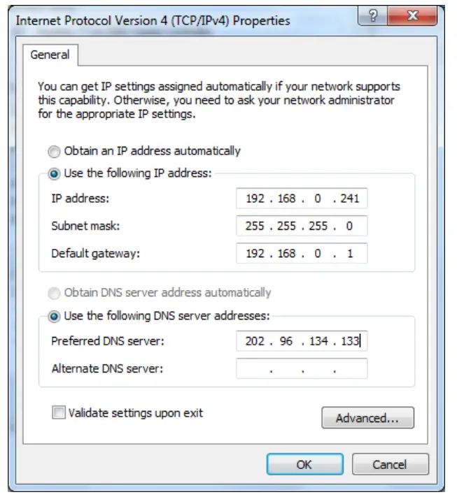
References
[xyz-ips snippet=”download-snippet”]