![]()
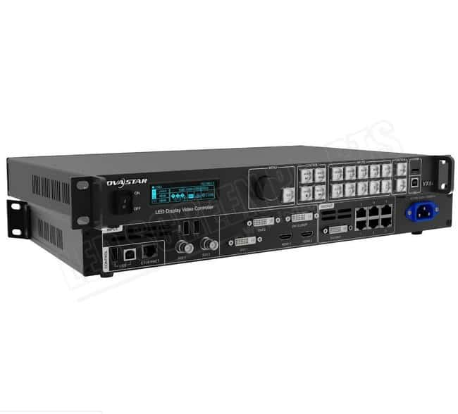
NOVASTAR All-in-One Controller User Guide
1. Applications
The VX1000 and VX600 support the following typical application scenarios. This guide uses the VX1000 as an example to illustrate.
- Work as a video controller
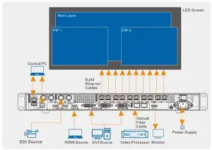
- Work as a fiber converter for long-distance transmission

- Quick Configuration
Prerequisites
- LED screen must be a regular screen.
- Cabinets of the screen must be regular cabinets with the same resolution.The following data flow settings are supported. During data flow settings, ensure that the physical connection of each port is along the same direction and downward to next one.
- During data flow settings, ensure that Ethernet Port 1 is at the beginning position of the whole physical connection.
ProcedureStep 1 Power on the VX1000 and LED screen.
step 2 On the home screen, press the knob to enter the main menu screen.
Step 3 Go to Screen Configuration> Quick Configuration to enter the quick configuration screen.
Step 4 Set Cabinet Row Qty and Cabinet Column Qty according to the actual row and column quantities of the cabinets.

Step 5 Rotate the knob to select Port 1 Cabinet Qty to set the quantity of the cabinets loaded by Ethernet port 1.

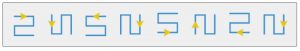
Step 6 Rotate the knob to select Data Flow (Front View) and press it, then select an appropriate physical connection for the cabinets.
During data flow settings, you can view the real-time effects of different data flow settings on LED display by rotating the knob. When you are satisfied with the LED display image, press the knob to save the settings.
3. Layer Operations
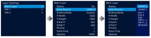
Add LayersStep 1 On the device front panel, locate and press the desired layer button in the CONTROL area, and then the bu1ton becomes flashing and the device screen displays the layer settings screen.Step 2 On the layer settings screen, rotate the knob to set the layer status to On to add a layer .

Step 3 Rotate the knob to select Input Source and press the knob to open the input sources pane. Select the desired input source for the layer and press the knob to confirm.
The layer parameters are illustrated as follows.
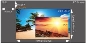
The greater the priority number is, the higher priority the layer has. In the above example, the main layer priority is 1 and the PIP priority is 2.
Switch Layer Input SourcesThe VX1000 offers two ways to switch the layer input source.
- Via menu operations
- Via front panel buttons
Via menu operationsOn the main menu screen, go to Layer Settings> Main Layer/PIP 1/PIP 2 > Input Source, and then select the desired source and press the knob to confirm.
Via front panel buttons
Step 1 On the device front panel, locate and press the desired layer button in the CONTROL area, and then the button becomes flashing and the device screen displays the layer settings screen.
Step 2 Press the desired input source button in the INPUTS area to switch the layer input source.

www.novastar.techAddress: 101 Block D-F, 01 Square, Xi’an Software Park, No. 72, 2nd Keji Road, Xi’an, Shaanxi, ChinaTel: +86 29-68216000
4. Preset Operations
The VX1000 supports up to 10 user-defined presets. You can save the layer layout, input source and more as a preset for future use.
Save Presets
PrerequisitesYou have completed the layer size, position and other settings.
Procedure
Step 1 On the main menu screen, go to Preset Settings> Preset 1 to open the preset operations window.
Step 2 Rotate the knob to select Save and press the knob to confirm.
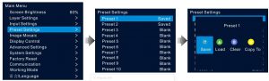
- Save: Save the current layer settings to a specified preset. If the target preset is a saved one, it will be overwritten.
- Load: Load and apply the selected preset to the LED screen.
- Clear: Clear all the layer data in a saved preset.
- Copy To: Copy the preset to another preset.
Load Presets
Step 1 On the main menu screen, rotate the knob to select Preset Settings and press the knob to enter the preset settings screen.
Step 2 Rotate the knob to select a saved preset and press the knob to open the preset operations window.
Step 3 Select Load and press the knob to apply the preset to the screen.
Note: When the device shows the Preset Settings screen, the number buttons on the device front panel a re lit. You can press a number button to quickly load a corresponding preset.
5. Backup Operations
The VX1000 supports three kinds of backup, including device backup, Ethernet port backup and input source backup.
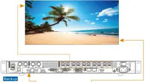
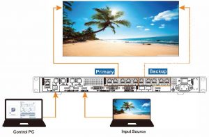
Device BackupThe connection diagram for device backup is shown in below. After the hardware connections are completed, go to Advanced Settings> Device Backup on the main menu screen, and then set the devices as the primary and backup devices respectively.

Ethernet Port BackupWhen setting the backup between the Ethernet ports, you need to complete it in NovaLCT. The connection diagram is shown on the right.
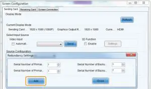
Log in to NovaLCT, and then go to Screen Configuration> Sending Card. Under the Sanding Card tab, set the backup between Ethernet ports in the Redundancy area.
Step 1 Click Add to open the Redundancy Settings window.
Step 2 Set the serial number of the primary port on the left and the serial number of the corresponding backup port on the right.
Step 3 Click Add to complete the backup settings of an Ethernet port .
Step 4 If needed, repeat Step 2 lo Step 3 to complete the backup settings for other Ethernet ports.

Input Source BackupWhen the input source hot backup function is turned on, if an input source fails, its backup source will be used seamlessly lo ensure the screen will not go black. On the main menu screen, go to Advanced Settings> Input Backup to enter the input source backup screen.
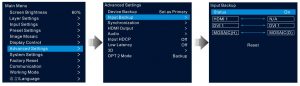
Step 1 Rotate the knob to turn on the input source backup function. On the left are the default input sources, and on the right you can set the backup sources.
Step 2 Rotate the knob to select the backup source on the right side and press the knob to expand the available source list, and then rotate the knob again to select the desired source and press the knob to confirm.
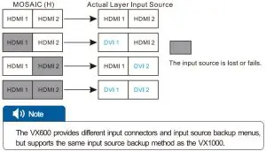
The two sources on both sides serve as the backup for each other.
- MOSAIC (H) indicates this mosaic source is composed of HDMI sources.
- MOSAIC (0) indicates this mosaic source is composed of DVI sources.
- After the backup settings for a mosaic source take effect, if any of the mosaic input sources fails, the backup rules are as follows:
6. Working Mode
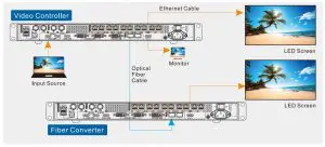
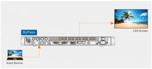
The VX1000 supports 3 kinds of device working modes: Video Controller (default), Fiber Converter and ByPass.
- Video Controller: The device works as an all-in-one controller offering both the video processing and control capabilities.
- In this mode, OPT 1 is used for either the input or output, and OPT 2 backs up or copies the output on the Ethernet ports.
- Fiber Converter: The device is used for long-distance transmission.
- In this mode, OPT 1 and OPT 2 are both used for input, and the Ethernet ports are used for output.
- ByPass: The device is used as a sending card to realize pixel-to-pixel display and meanwhile reduce the latency.
On the main menu screen, select Working Mode and press the knob to enter the device working mode screen.

OPT Port Descriptions
- OPT 1 is used for either input or output depending on the connected device. When the N9, VE 7 or other device that uses OPT port to transmit videos is connected to OPT 1 of the VX1000, OPT 1 is used for input.
- When a fiber converter is connected to OPT1 of the VX1000 or the VX1000 works as a fiber converter, OPT 1 is used for output and transmits data on the 10 Ethernet ports.
Device Connections in Different Working Modes
[xyz-ips snippet=”download-snippet”]