NOVASTAR LED Video Controller
StatementYou are welcome to use the products from Xi’an NovaStar Tech Co., Ltd. (hereinafter referred to as Novastar). It is our great pleasure to offer this manual to help you understand and use the product. We strive for precision and reliability during the compilation of this manual, and the contents of this manual are subject to change without notice. If you have any problem in use or you have any suggestion, please feel free to contact us according to the contact information provided in this manual. We will do our utmost to satisfy your needs. Also, we would like to express our sincere thanks to your suggestions and make assessment as soon as possible for adoption.
CopyrightNo part of this manual may be reproduced or transmitted in any form or by any means without prior written consent of Xi’an NovaStar Tech Co., Ltd.
Trademark![]() is a registered trademark of NovaStar Tech Co., Ltd.
is a registered trademark of NovaStar Tech Co., Ltd.
Safety StatementTo avoid potential hazards, please use this equipment according to the regulations. In case of damages, non-professionals should not disassemble it for maintenance without permission. Please contact the after-sales department of the company.
![]() High voltage danger: The operating voltage of this product is 100-240V AC.
High voltage danger: The operating voltage of this product is 100-240V AC.![]() Grounding: This production is connected to ground via the ground wire of power supply. Please ensure good grounding of grounding conductor.
Grounding: This production is connected to ground via the ground wire of power supply. Please ensure good grounding of grounding conductor.![]() Electromagnetic interference: The device should be kept far away from magnets, motors and transformers.
Electromagnetic interference: The device should be kept far away from magnets, motors and transformers.![]() Moisture proof: Keep the equipment in a dry and clean environment. In case of liquid immersion, please pull the plug immediately.
Moisture proof: Keep the equipment in a dry and clean environment. In case of liquid immersion, please pull the plug immediately.![]() Keep away from flammable and explosive dangerous goods.
Keep away from flammable and explosive dangerous goods.![]() Prevent liquids or metal fragments from being immersed into the machine to avoid safety accidents.
Prevent liquids or metal fragments from being immersed into the machine to avoid safety accidents.
1 Model description
ModelVX4VX4S
Description(input interface type)DVI×2, VGA×3, CVBS×3, HDMI×1, DP×1DVI×1, VGA×2, CVBS×2, HDMI×1, DP×1, SDI×1
Tips: VX4 has different type and number of interface with VX4S, but their functions and specifications are basically the same. In this manual, VX4 is described as the example.
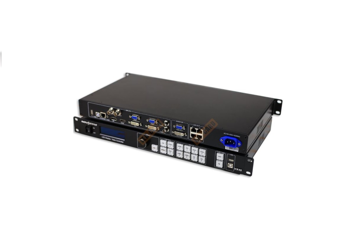
2 Appearance
Front Panel
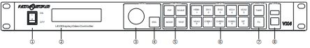
(1):Power switch(2):Operation screen (Please see the section-Main Interface for detail).(3):Knob To press knob means Enter or OK, rotating knob represents selection or adjustment.(4):ESC Escape current operation or selection.(5):Four control keyboard shortcutsPIP: PIP Turn-on/off. The lighting of this key represents the turn-on of PIP; otherwise, PIP is turned off.SCALE: Picture zoom turn-on/turn-off. The lighting of this key represents the turnon of zoom function; otherwise, zoom function is unavailable.MODE: Shortcut menu of loading or storage of display model. The key is light when entering the model or shortcut menu, in case of exiting, the key is not bright.TEST: Shortcut of turn-on/off of testing picture. In case of entering testing picture, the key is bright; otherwise, the key is not bright.(6):Shortcut keys for switching of 10 signal input sources. Short press to set as the main screen input source, and long press to set as PIP input source. The key is bright after press when the video source has signal; the key flashes when the input of video source has no signal. The setting result can be checked while setting on the display screen and OLED screen.Note: You can enter numbers, such as layer size and offset value, by pressing the number buttons. The number button will be highlighted after pressed.(7): Function keysTAKE Display switching shortcut key. After short pressing TAKE key, PIP will be opened; if it has been opened, the switching between MAIN and PIP will be realized. Fn: Custom shortcut key.(8):Flat mouth (Type A, female USB) is USB interface, which connects U disk; Square mouth (Type B female USB) is USB controlling interface, communication with PC.
Input SourceAudio — Audio InputDP — DP InputHDMI — HDMI InputCVBS1~CVBS3 — 3-Channel PAL/NTSC TV composite video InputsDVI -1~DVI-2 — 2-Channel DVI InputsVGA1~VGA3 — 3-Channel VGA InputsOutput InterfaceDVI LOOP — DVI LOOP OutputMonitor -DVI OUT1 — DVI Monitoring Interface 1Monitor -DVI OUT2 — DVI Monitoring Interface 2LED Out 1,2,3,4 — 4 Gigabit Ethernet outputs. Only Ethernet port 1 supports audio output. When the multifunction card is connected for audio decoding, the multifunction card must be connected to Ethernet port 1.Controlling Interface ETHERNET — Network Control (Communication with PC, or Access Network)Type B, female USB — USB Control (Communication with PC, or Cascade IN)Type A, female USB — USB Cascade OUT
PowerAC 100-240V 50/60HZ — AC Power InterfaceTips: The two USB interfaces ( typeA) on front panel and rear panel are both forbidden to connect with the PC directly.
3 Signal connection
Connect the required hardware equipment reference with the interface descriptions of the previous chapters.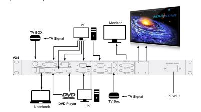
If it is required to control more than one set of VX4, please connect them according to the following figure.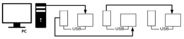
4 Dimension

5 Operating motion instruction
Knob:
- Press the knob under the main interface to enter the operation interface menu;
- Rotate the knob to select menu or press the knob under the operation interfaceof the menu to select current menu or enter submenu;
- Rotate the knob to adjust the parameter after selecting the menu with the parameter; press the knob again for confirmation after adjustment. ESC: Return key, exit current menu or operation. Key lock/unlock: long press knob and ESC key simultaneously.
6 Main Interface
After starting the controller, the main interface of OLED display is as follows:
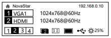
First row: Company name; the name and IP of the product are shown alternately; Second row: Main screen 1; signal source; input source signal format; Third row: PIP 2; signal source; input source signal format; Forth row: Status bar. the meanings of all icons are shown below.

![]() Sign of press key lock. When this icon appears at the main interface, it is in locking state for key and knob functions.
Sign of press key lock. When this icon appears at the main interface, it is in locking state for key and knob functions.
7 Operation instruction
The functions of VX4 are powerful with very simple operation, and multiple operations can be completed with a knob and a return key. The design of more than one shortcut keys makes operations more efficient.Generally, the LED display can be used normally, and the brightness is moderate after conducting the following four steps: Input settings Screen settings Brightness Output settings. Other menus such as screen control and senior setting can help users better control LED display.See the following section for details of operations.
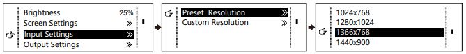
Step1: Input Settings
Set resolution of input source signal. Resolution can be directly set and changed for digital input interfaces DVI, HDMI and DP. Resolution can only be modified with other input methods on input devices.
Input resolution can be set in two methods:
Method one: Preset Resolution.
Selection is made in preset resolution of the controller. If there is no preset resolution, you can select the second method and customize resolution.
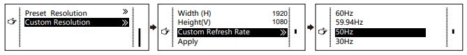
Method two: Custom Resolution.Set Horizontal Res, Vertical Res and Custom· refresh rate and then select “Apply” and press the knob for application. If the application is not confirmed, custom resolution is invalid.
Step2: Screen SettingsThe precondition of Screen setting in shortcut is that the screen must be regular rectangle (not special-shaped), cabinet must be regular rectangle and the size of each cabinet are identical.Step 1The screen being power-on, if the cabinet is in normal display, enter into
Step 2; if the cabinet is in abnormal display, first, load the cabinet file, and save it to the receiving card; see detailed operation in Advanced Settings ;
Step 2Return to the “Screen Settings” submenu. Rotate the button to switch to submenus of other options respectively to perform configurations, as shown in the following figures:
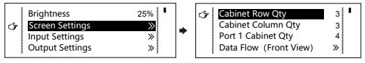
Step 3Set Cabinet Row Qty and Cabinet Column Qty according to the actual situation of the screen;Step 4Set Port1 Cabinet Qty. The device has some limitations on the cabinet quantity of ports. For details, see precautions for screen settings;Step 5Set the Data Flow (Front View). Pay attention to precautions for screen settings c), d) and e) below.
Precautions for screen settings:
(a) If the number of ports with loads is n (n4), the first n-1 ports must load the same number of cabinets, which must also be an integral multiple of the number of cabinet rows or columns and be greater than or equal to the number of cabinets for the nth ports.
Example:For example, if port 1, port 2, port 3 have loads, port 1 and port 2 must have the same number of cabinets, which must also be an integral multiple of the number of cabinet rows or columns. Therefore, you only need to set port 1 cabinet Qty according to the actual situation when setting the screen. The number of receiving cards port 3 loads must be smaller than or equal to port 1.
(b) In the case of special-shaped cabinets, different cabinet sizes and specialshaped screen, the NovaLCT-Mars software is required to be connected to configure the screen.
(c) During the Data Flow setting, you can rotate the button to see the effects of different data flow on the screen in real time. If you are satisfied with the effect of current data flow, you must press the button to save the setting. You can press the ESC to exit from the current operation.
(d) During the Data Flow setting, you must ensure that the data flow of each port is downward in the same direction.
(e) During the Data Flow setting, you must ensure that Port 1 is the start position of the whole data flow connection.
VX4 can load 2.3 million (2048×) pixels in maximum. The width of lateral load can reach to 3840 pixels in maximum (3840×); the longitudinal load can reach to 1920 pixels in maximum (1920 ).
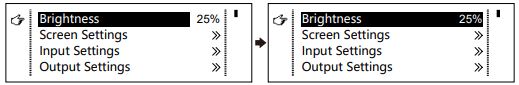
Setp3: BrightnessReturn to the main menu interface. Press the Knob to select the corresponding value of Brightness. You can rotate the Knob to adjust the value at this time.
Setp4: Output SettingsOutput settings are divided into three cases:First one: disable Scaling, i.e., the sizes of output image and input image are the same, and the original scale output is used. If the input resolution is smaller than the LED display in one direction, LED display may not become bright in this direction; if the input resolution is greater than the LED display in one direction, the input contents may not be displayed completely in this direction. This option is applicable to the application scenarios requiring point-to-point display. Horizontal offset and vertical offset of images can be set according to the needs, and at this time the displayed contents may move to the left or top at the LED display.At this point [Scaling] is disabled.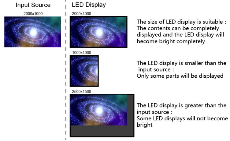
Second one: Auto Fit At this point [Scaling] is enabled, and [Auto Fit] is enabled.When enabling [Auto Fit], the input contents will be fully zoomed to the size of LED display, and the input contents will be adaptive to the size of LED display. This mode is suitable for full-screen playback of the contents.Third one: Custom Scaling At this point [Scaling] is enabled, while [Auto Fit] is disabled.The following steps should be performed for custom scaling:
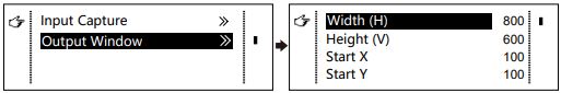
Step 1Set the input Capture, i.e., capture part of the interesting screens from onestarting point of inputting image and display it on LED display. It is generally required to set Horizontal Res (smaller than or equal to the lateral resolution of input source), Vertical Res (smaller than or equal to the vertical resolution of input source), horizontal X and vertical Y.
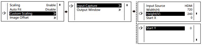
Step 2
Set output window, the size of window is smaller than or equal to the size of LED display; after setting the window, the images can only be adaptive to the displayed size within the range of window. This option is applicable to the application scenarios requiring reserving border at the LED display or restricting playing area.
After setting according to the above two steps, the captured contents will only be input and displayed at the set area on the LED display, as shown below:
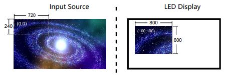
Image MosaicWhen the display screen is huge, two or more VX4 need to be cascaded for loading the huge screen; Choose the method of Image Mosaic: Equal Division, Unequal Division.
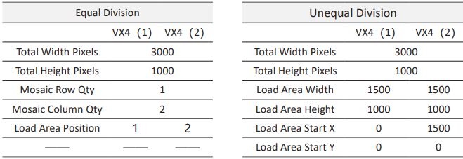
- Equal Division: Each VX4 has same load area. It is only required to set the total pixelpoints, rows ,columns of the big screen and the serial No. of each VX4.
- Unequal Division: Each VX4 could have different load area . It is required to setthe total pixel points and the load area size as well as load area staring position of each VX4.
Image Mosaic example: The total number of pixels of LED display is 3000×1000, exceeding the load capacity of single VX4. Two sets of VX4 are used for Image Mosaic processing. The connection method is shown in the right figure.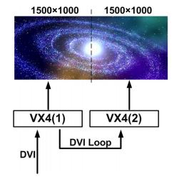
Please choose Equal Division or Unequal Division while setting detailed parameters. The specific parameter settings are shown in the following tables.
Advanced SettingsSeveral setting options of main functions are included in advanced settings, as shown in the figure below. Operation of each function will be detailed for users in the following text.
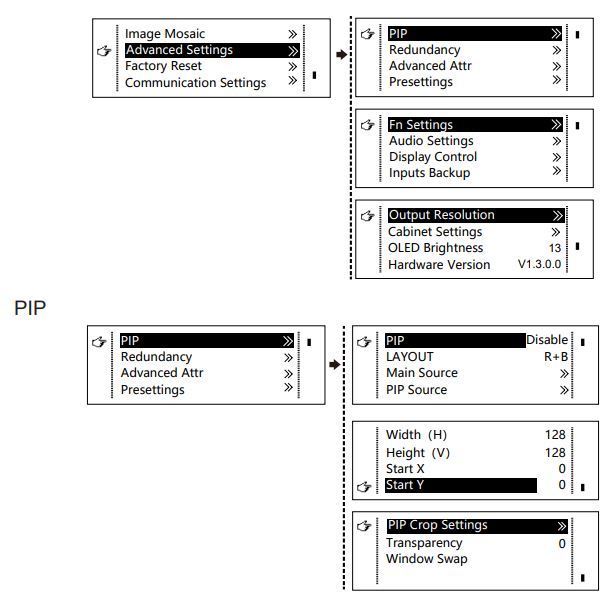 Control the turn-on/off of PIP, Set input source of main screen and PIP, as well as parameters of PIP.
Layout: the position of PIP relative to main screen, including eight modes of layout such as Custom, Left Top, Left Bottom, Right Top etc. When choosing any mode except Custom , the values of horizontal and vertical offset of PIP are able to adjust to the corresponding values of layout automatically. The meaning of each layout mode is shown below:
- Custom refers to that the size and position of PIP need to be set. Left Top,
- Left Bottom, Right Top, Right Bottom, Center refer to that PIP overlapswith the top-left corner, bottom-left corner, top-right corner, bottom-right corner, and center of main screen.
- Top Bottom, Left Right refer to that main screen and PIP are distributed from top to bottom or left to right.
Main source/PIP source: Input source switching of main picture and PIP is the same as the role of input source switching on the front panel.Horizontal Res : Horizontal offset of PIPVertical Res: Vertical offset of PIPHorizontal X: Horizontal width of PIPVertical Y: Vertical height of PIP
PIP Crop Settings: Picture is cropped from the set starting position and is displayed on PIP and its size is set horizontal width and vertical height.
Enable this function and then set horizontal width, vertical height, horizontal X and vertical Y.
Transparency: the transparency of PIP
Window Swap: swap play content of main screen and PIP.
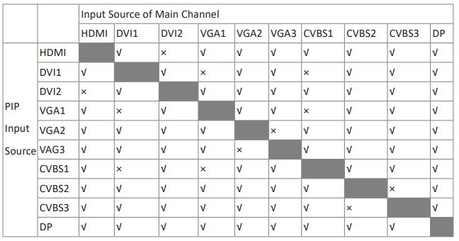
The Conflict List of PIP Signal SourceVX4
Input Source of Main Channel
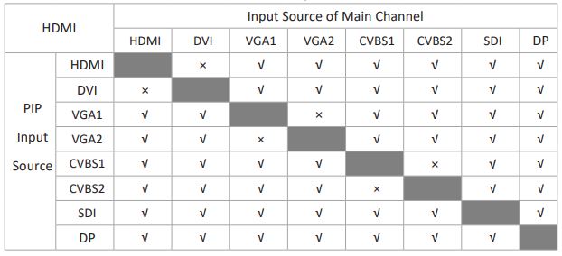
The Conflict List of PIP Signal Source (VX4S)
RedundancySet this controller as primary or backup mode.Advanced Attribute
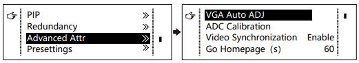
- VGA Auto ADJ: Sampling parameters of VGA input signal are automatically adjusted so that the VGA picture is clear and complete. Select this menu and then press the knob once and perform VGA automatic adjustment once. (VGA1 does not support this feature)
- ADC calibration: when analog signal accesses, processors that are not calibrated by ADC may have defects such as color cast or picture dark. VX4 can automatically make ADC calibration based on input analog signal (including CVBS and VGA) to solve the problems above. Select this menu and then press the knob once and perform ADC calibration once.
- Video Synchronization: allow that the input and output of VX4 are synchronous.
- Go Homepage(s): The time period during which the system stops at currentinterface and then automatically returns to home screen when there is no operation. The system default value is 60s.
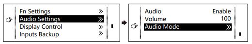
PresettingsSave the current configuration parameters as Presettings. The Presettings can be directly loaded next time, and 10 Presettings are saved by default.Custom ButtonFn Settings. The functions of custom button include Black Out, FreezeVGA Auto ADJVideo Synchronization. Press Fn key to directly conduct the function switch.Audio SettingsControl the enabling /disenabling of Audio, volume and Audio mode.For example, when using the audios input via Audio In port, it is required to enable audios first and then select the Audio mode to be fixed; when using the Audio from HDMI, set the Audio mode to be accompanied after enabling audios and then switch source to HDMI, and the Audio we hear comes from HDMI.
Display Control
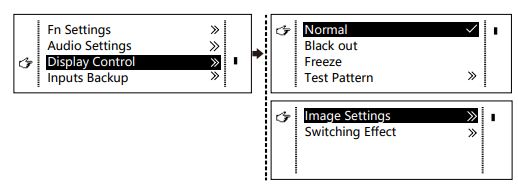
- Normal: Normally display. Blank Out: The display is blank
- Freeze: The current playlists are frozen.
- Testing Pattern: There are eight kinds of testing screens in total, including purecolor and lines.
- Image Settings
Contrast, Saturation, Hue, Color Temperature, Red, Green, Blue and Gamma value are set according to the requirements. After they are adjusted to satisfaction, the parameters should be saved.
- Switching Effect:Set the effects when switching screens, including Quick switch, Fade, Shrink Center, Shrink Left Top, Zoom Center, Zoom Left Top and turning off. After selecting the desired effect, it will take effect after pressing the knob.
Tips: When enabling PIP function, the switching effect will automatically disappear. Only when PIP function is turned off, the special effect function of channel switching can take effect.Inputs BackupTo specify backup for input source and automatically switch to backup source if the signal of input source has faults, which makes it more reliable.
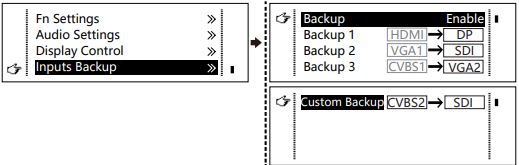
HDMI→ DP Indicating that DP has been set as the backup of HDMI and main input source(which cannot be changed) is in left side of the arrow while backup(which can be changed) is in the right side; Both main input source and backup can be customized in Custom mode.Output ResolutionThis function can be used to set the the output resolution of monitoring. Users can set the function according to actual use and choose either Reset Resolution or Custom.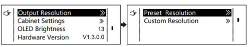
Cabinet Settings
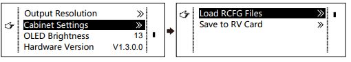
Load Cabinet Files
VX4 is connected with PC. NovaLCT-Mars runs on PC and the cabinet setting file saved previously is imported into controller.
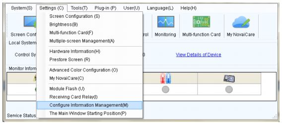
1 ) Save cabinet configuration file.
After receiving card is configured, click ![]() and save cabinet configuration file (.rcfg) to local file on PC.
and save cabinet configuration file (.rcfg) to local file on PC.

2 ) Cabinet configuration file is imported into VX4. -14-
3 ) Load Cabinet Files.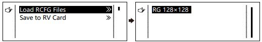
Save to RV Card All current configurations about the recieving card of VX4 are saved into receiving card and will not be lost after power fault.
OLED BrightnessAdjust the gray scale of OLED display.Hardware VersionView the hardware version of VX4. If new version has been published, LCT-Mars can be connected via PC and the hardware program of VX4 can be upgraded
Factory ResetReset to factory default setting.
Communication SettingsSet the communication mode and network parameter of VX4. The communication modes include USB priority and LAN (local area network) priority. When VX4 is connected to USB control and LAN control interface simultaneously, USB takes priority in the settings, adopts USB control; otherwise, LAN takes priority in the settings, adopts LAN control. The network parameter can be set both manually and automatically. Ensure that the IP address is not conflict with other equipment when setting parameter manually.
LanguageSwitch Language.
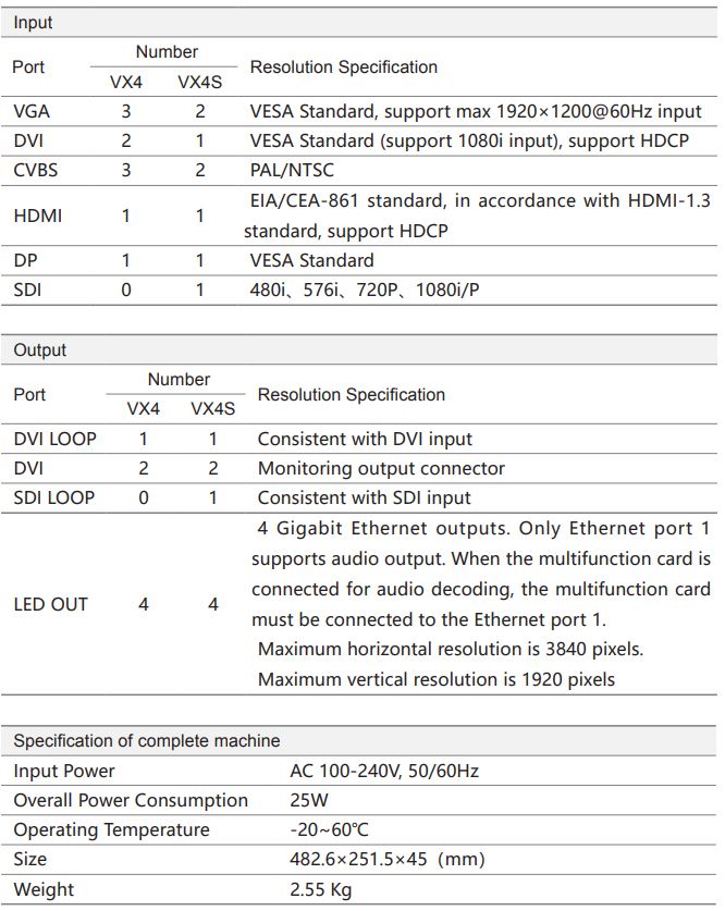
8 Specifications
9 FAQ
QuestionsLED display is offMethodsInspect whether the power connection is correct and the switch has been turned on;Play the Self test image and confirm whether the connection of LED is correct and works normally;Inspect whether VX4 output has signal and shows blank screen;Inspect whether the mode and parameter of screen configuration are correct;
QuestionsMonitoring port output is abnormalMethods
Check whether there is image input in input channel and whether it is correctly displayed;Check whether PIP has been turned on, whether there is signal input in 2 channel and whether it is correctly displayed;Check whether monitoring output is connected correctly and it is not loose;Please confirm whether Monitor supports the output resolution of VX4;Try to cut off the power of equipment and restart it, reset VX4 and operate again;
QuestionsThe phase of VGA input offsetMethods
Perform VGA Auto ADJ;
QuestionsPIP display is abnormalMethods
Check whether there is signal input in 2 channel and it is normally displayed; Check PIP and confirm whether parameter setting is normal;
QuestionsFading is abnormalMethodsCheck whether the Switching effect has been enabled;
QuestionsImage Mosaic is abnormalMethodsCheck whether the VX4 Image Mosaic switch has been turned on and whether Image Mosaic parameters settings is correct;Check whether input signal source is normal;
QuestionsSound is abnormalMethods
Check whether the volume settings is appropriate;Check whether the Audio mode setting is correct;Confirm VX4 is well connected to multifunction card, and the corresponding output port icon on the main interface has been highlighted; confirm whether the audio output mode of multifunction card is HDMI mode (it is required to connect LCT for confirmation and setting);
Please preliminarily investigate problems according to the above steps; if you cannot eliminate the problems, please contact the local dealer or our company’s customer service personnel.There is high voltage inside the machine. In order to guarantee your safety, please do not maintain the processor by yourself.
[xyz-ips snippet=”download-snippet”]