NOVASTAR NovaPro UHD All In One Controller User Guide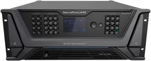
Introduction
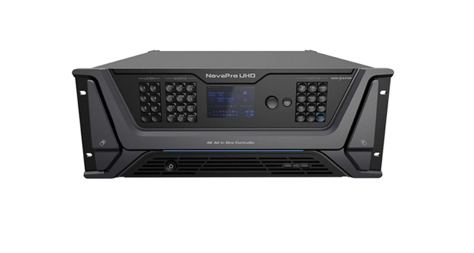
The NovaPro UHD is a new al-in-one controller developed by NovaStar. By integrating video processing, video control and LED screen configuration functions into one controller, this product is capable of receiving a variety of video signals, processing and sending images of resolutions up to ultra HD
With the built-in Master VI smart platform, the NovaPro UHD supports layer creation, property settings, and screen configuration via simple mouse, keyboard, and monitor operations.
The NovaPro UHD supports sending of processed video to LED display through Neutrik Ethernet ports or fiber optical connectors. With powerful video processing and sending capabilities, this product is well suited for high -end rental applications, stage control systems, and the-pitch LED displays.
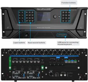
|
Input |
||
| Connector | Qty | Description |
| 12G-SDI | 4 | Supports ST-2082-1 (12G), ST-2081-1 (6G), ST-424 (3G) and ST-292 (HD) input signals.Input resolutions up to 4K and downwa rd compatible Support 12G-SDI loop output |
| DP 1.2 | 1 | Input resolution up to 4K (8K•) and downward compatible, HDCP 1.3 compliantDoes not support interlaced signal inputs |
| HDMI 2.0 | 1 | Input resolution up to 4K (8K*) and downward compatible, HDCP 1.4 and HDCP 2.2 compliant, loop output Does not support interlaced signal inputs. |
| HDMI 1.3 | 4 | 4 * HDMI 1.3: Each with resolution up to 1920* Can be changed to D_4 DVI input cardThe default option is D_4 HDMI input card Support HDCP 1.3 Supports interlaced signal inputs |
|
Outout |
||
| Connector | Qty | Description |
| Ethernet port | 16 | Neutrik Gigabit Ethernet outputs |
| OPT 1—4 | 4 | 4 10G fiber optical output connectors with copy and hot backup modes
|
| MVR | 1 | HDMI 1.3 connector, used as monitoring connector of Multi Viewer to monitor input source, PVM, PGM or perform mixed preview |
| AUX | 1 | HDMI 1.3 connector, used as auxiliary output connector for |
|
Control |
||
| Connector | Qty | Description |
| ETHERNET | 1 | Connect to th PC for communication or connect to the network |
| USB | 3 | 1 x USB-BConnect to the PC for device debugging.2 * USB-A:Insert a USB drive to perform system update. Connect a mouse or keyboard.Output connector for device cascading. |
| GENLOCK IN-LOOP | 1 | Connect a synchronization signal source to synchronize the |
| CONTROL UI | 1 | Connect to a monitor for human-machine interaction. |
Applications
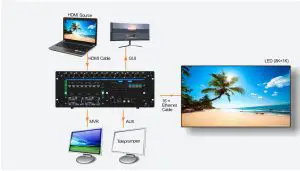
- 1 NovaPro UHD unit for image mosaic

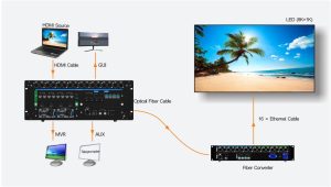
- Remote Transmission – 1 NovaPro UHD unit only

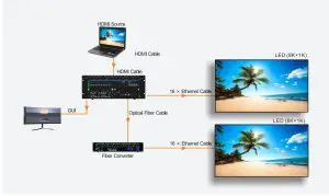
- Remote Transmission – 1 NovaPro UHD unit for copy output mode

- Remote Transmission – 1 NobaPro unit for hot backup output mode
 Note: If the Ethernet cable of the NovePro UHD or fiber converter converter is disconnected ,the LED screen can still work normally.
Operations
Basic operations of the NoyaPro UHD includes configuring screens. adcfng layers and selecting input sources. C
Quick Configuration
Preconditions
- LED screen must be a regular screen.
- Cabinets of the screen must be regular cabinets with the same resolution.
- The flowing data flow settings are supported. During data flow settings, you must ensure that the physical connection of each port Is along the same direction and downward to next one.

- During data flow settings, you must ensure that the Ethernet Port 1 is at the beginning position of the whole physical connection.
Procedure
- Step 1 Power on the LED screen.
- Step 2 On the home screen, press the knob to enter the main menu screen. Then rotate the knob to choose Screen Settings > Quick Configuration to enter the quick configuration screen.
- Step 3 Set Cabinet Row Qty and Cabinet Column Qty according to the actual row and column quantities of the cabinets.

- Step 4 Rotate the knob to select Port 1 Cabinet Qty to set the quantity of the cabinets loaded by Ethernet port 1.NoteThe quantities of the cabinets loaded by Ethernet pats 1-15 cost be the same. The 3 of the cabinets boded by Ethernet port 16 should be no greater than that loaded by Ethernet 1-15. The quantity of cabinets boded by each Ethernet port must be an liege:multiple of ‘ Row Qty or Cabinet Column Qty of the screen.
- Step 5 Rotate the knob to select Data Flow (Front View) and press it, then select an appropriate physical connection mode of the cabinets. During data flow settings, you can view the real-time effects of different data flow settings on LED display by rotating the knob. When you are satisfied with the LED display image, press the knob to save the settings; when you are not satisfied, press ESC button to exit the current operation and the settings will not be saved.
- Step 6 Press ESC button to exit the quick configuration screen.
- Step 7 Rotate the knob to select Save to RV Card and press the knob to send and save the screen configuration file to the hardware.
Adding Layers
- Step 1 Rotate the knob to choose Layer Settings > Layer > Select Layer > Layer 1 to add the current layer.
- Step 2 Rotate the knob to choose Status >Onto enable the layer 1.
- Step 3 Rotate the knob to select Input Source and select the desired input source based on your actual needs.

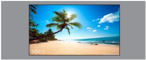
After a layer is added successfully, the size and input source of the layer on the LED screen are shown in below.
Preset Settings
The NovaPro UHD supports 16 presets. You can save the ctsrent layer layout to a preset and load the preset as needed.
- Step 1 Rotate the knob to choose Preset Settings > Preset 1. Then the Preset window appears.
- Step 2 Rotate the knob to select Save, Load, Clear and Copy To.


Master VI Operations
You can use the embedded Master VI by connecting the GUI comedy on the device rear panel or installing the software on your PC.
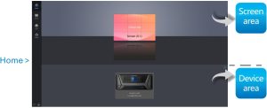
- Display sizes and names of the configured screens.
- Click a screen to enter its Screen function page.
- Display names and serial numbers Of currently connected devices.
- Click a device to enter its Layer function page.


Perform smart screen configurations.
On the Edit tab page, select the Ethernet ports under Device.
- Choose Edit > Cabinet Management and add a single cabinet or a batch of cabinets to the edit area.
- Choose Edit > Cabinet Connection to connect the added cabinets.
- Click the Send button on the tool bar to send current configurations to the receiving card.
- Click the Save to HW button on the tool bar to save current configurations to the receiving card.

Pelican layer configurations for video sources.
Click an input source and drag it to the edit area to add its corresponding layer. Drag the layer corner to resize it.
- Change the layer parameters on the right properties pane, such as cropping and mask.
- Click the Take button or move the T-bar to send the PVW images to the screen.
Reset the device data to the factory defaults as required. Select either to save the IP or save both the IP and EDID during reset.
Set the administrator password 1 for user permission control.
Specifications
|
Overall Specifications |
||
| Connector | Qty | Description |
|
Power connector |
2 | 100-240V-,50/60Hz, 7.2A-3.5A, Dual power supply design |
|
Power consumption |
180W | |
|
Operating temperature |
-10°C – 60°C | |
|
Operating humidify |
0% RH – 80% RH | |
|
Storage humidity |
0%RH – 95%RH | |
|
Dimensions |
4U standard chassis | |
|
Net weight |
21 kg |

[xyz-ips snippet=”download-snippet”]

 Note: If the Ethernet cable of the NovePro UHD or fiber converter converter is disconnected ,the LED screen can still work normally.


