NOVASTAR VX2U LED Display Video
Controller User Manual
StatementWelcome to use the product from Xi’an NovaStar Tech Co., Ltd. (hereinafter referred to as “Novastar”). It is our great pleasure to offer this manual to help you understand and use the product. We have striven for precision and reliability during the compilation of this manual. Contents of this manual are subject to change without notice. If you have any problem or suggestion in use, please feel free to contact us according to the contact information provided in this manual. We will do D our utmost to satisfy your needs. We would like to express our sincere appreciation T and make an assessment of your suggestions for adoption as soon as possible.
CopyrightCO No part of this manual may be reproduced or transmitted in any form or by any means without prior written consent of NovaStar.
Trademarkis the registered trademark of NovaStar.
SafetyTo avoid potential hazards, please use this unit according to the regulations. In case S of damages, non-professionals are not allowed to disassemble it for maintenance. A Please contact the after-sales department of NovaStar.
1 Model Description
Tips: The number, types, functions and specifications of the interfaces of VX2U and VX4U are basically the same. In this manual, VX4U is described as an example.
2 Appearance
Front Panel
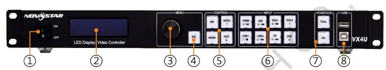
- Power switch
- Operation screen(Please see details in the Chapter: Main Interface.)
- Knob: Pressing the knob means Enter or OK and rotating the knob represents selection or adjustment.
- ESC: Escape current operation or selection.
- Four control shortcuts PIP: Enable/Disable PIP. The indicator light on denotes PIP is A enabled, otherwise, PIP is disabled.SCALE: Enable/Disable full screen scaling. The indicator light on denotes the full screen scale function is enabled, otherwise, the full screen scale function is unavailable.MODE: Shortcut menu for loading or saving models. The indicator light is on when entering the model or shortcut I’A menu. The indicator light is off after exiting. XTEST: Shortcut for enabling or disabling test pattern. In caseNote You can enter numbers, such as layer size and offset value, by pressing the number buttons. of entering test pattern, the indicator light is on, otherwise, The number the light is off button will be
- Shortcuts for switching of 8 signal input source. Press to set highlighted as main screen input source and long press to set as PIP input after pressed. source. The setting result can be viewed on the operation screen.
- Function keysTAKE: Shortcut for screen switching. After pressing TAKE key, PIP will be enabled. Switching between MAIN and PIP will be realized after it is enabled.Fn: Custom shortcut key.
- Flat mouth (Type A USB) is USB interface for connecting USB drive;Square mouth (Type B USB) is USB control interface to connect PC for communication.
Rear Panel
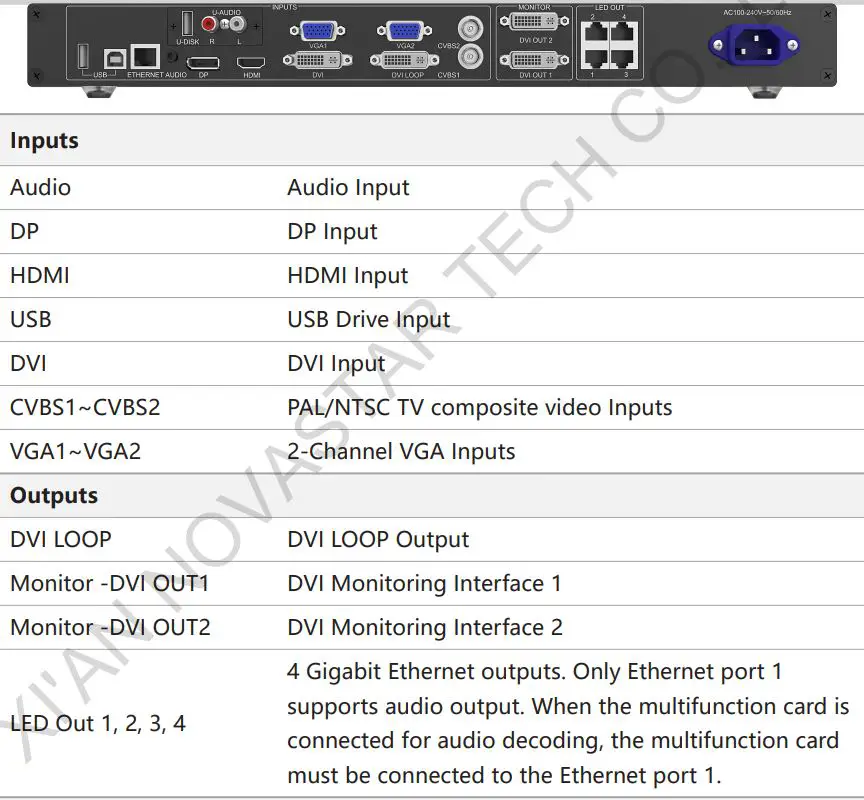
3 Signal Connection
Connect the required hardware equipment’s referring to the interface description of the previous chapters.
4 Dimensions
5 Operating Motion Instruction
Knob:
- A Press the knob in the main interface to enter the interface of menu operation;
- Rotate the knob to select menu or press the knob under the operation interface of menu to select current menu or enter submenu;
- Rotate the knob to adjust the parameter after selecting the menu with parameter; press the knob again for confirmation after adjustment.ESC: Return key, exit current menu or operation.Key lock/unlock: long press knob and ESC key simultaneously.
6 Main Interface
After starting the controller, the main interface of OLED display is as follows:
First row: Company name; the name and IP of the product are shown alternately;Second row: Main screen 1; signal source; input signal format;Third row: PIP 2; signal source; input signal format;Forth row: Status bar. the meanings of all icons are shown below.
 7 Operation Instruction
VX4U has powerful functions and is easy to operate. All operations can be completed T through a knob and a return key. The design of shortcut keys makes the operations S more efficient.Generally, LED display can work normally, and the brightness is moderate after V following four steps: Input Settings→ Screen Settings → Brightness →Output Settings. Other menus such as display control and advanced settings can help users better control the LED display. N See the following section for detailed operation.
Step1: Input Settings
Set resolution of input signal. Resolution can be directly set and changed for digital input interfaces DVI, HDMI and DP. Resolution can only be modified with other input methods on input devices. Input resolution can be set through two methods:
Method I: Preset Resolution.Selection is made in preset resolution of the controller. If there is no preset resolution, you can select the second method and customize resolution.
![]()
Method II: Custom Resolution.
Set Horizontal Res, Vertical Res and Custom· refresh rate and then select “Apply” and press the knob for application. If the application is not confirmed, custom resolution is invalid.
![]()
Step2: Screen Settings
The precondition of Screen setting in shortcut is that the screen must be regular C rectangle (not special-shaped), cabinet must be regular rectangle and the size ofeach cabinet are identical.Step 1 The screen being power-on, if the cabinet is in normal display, enter into Step 2; if the cabinet is in abnormal display, first, load the cabinet file, and TE save it to the receiving card; see detailed operation in Advanced Settings ;
Step 2 Return to the “Screen Settings” submenu. Rotate the button to switch to submenus of other options respectively to perform configurations, as shown TA in the following figures:
![]()
Step 3 Set Cabinet Row Qty and Cabinet Column Qty according to the actual situation of the screen;
Step 4 Set Port1 Cabinet Qty. The device has some limitations on the cabinet I ‘quantity of ports. For details, see precautions for screen settings;
5 Set the Data Flow (Front View). Pay attention to precautions for screen settings c), d) and e) below.
Precautions for screen settings:
(a) If the number of ports with loads is n (n≤4), the first n-1 ports must load the same number of cabinets, which must also be an integral multiple of the number of cabinet rows or columns and be greater than or equal to the number of cabinets for the nth ports.
Example:For example, if port 1, port 2, port 3 have loads, port 1 and port 2 must have the same number of cabinets, which must also be an integral multiple of the number of cabinet rows or columns. Therefore, you only need to set port 1 cabinet Qty according to the actual situation when setting the screen. The number of receiving cards port 3 loads must be smaller than or equal to port 1
(b) In the case of special-shaped cabinets, different cabinet sizes and special-shaped screen, ., the Novato-Mars software is required to be connected to configure the screen.
(c) During Data Flow setting, you can rotate the button to see the effects of different data flow on the screen in real time. If you are satisfied with the effect of current data flow, you must press the button to save the setting. You can press the ESC to exit from the current operation.
(d) During Data Flow setting, you must ensure that the data flow of each port is downward in TE the same direction.
(e) During Data Flow setting, you must ensure that Port 1 is the start position of the whole data flow connection.
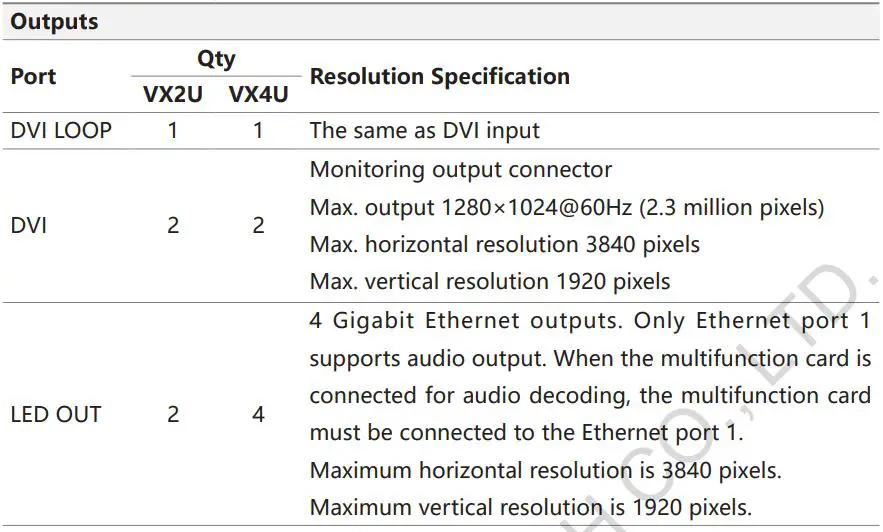
VX4U can load 2.3 million (2048×) pixels in maximum. The width of lateral load can T reach to 3840 pixels in maximum (3840×); the longitudinal load can reach to 1920 S pixels in maximum (1920 ).
Setp3: Brightness
Return to the main menu interface. Press the Knob to select the corresponding value of Brightness. You can rotate the Knob to adjust the value at this time.
![]()
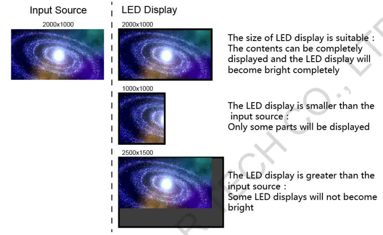
Setp4: Output Settings
Output settings are divided into three cases:First one: disable Scaling, i.e., the sizes of output image and input image are the same, and original scale output is used. If the input resolution is smaller than the LED display in one direction, LED display may not become bright in this direction; if the input resolution is greater than the LED display in one direction, the input contents may not be displayed completely in this direction. This option is applicable to the application scenarios requiring point-to-point display. Horizontal offset and vertical offset of images can be set according to the needs, and at this time the displayed contents may move to the left or top at the LED display.At this point [Scaling] is disabled.
Second one: Auto Fit. At this point [Scaling] is enabled, and [Auto Fit] is enabled. TA When enabling [Auto Fit], the input contents will be fully zoomed to the size of LED S display, and the input contents will be adaptive to the size of LED display. This mode A is suitable for full-screen playback of the contents.Third one: Custom Scaling At this point [Scaling] is enabled, while [Auto Fit] is O disabled.
The following steps should be performed for custom scaling:Step 1 Set the input Capture, i.e., capture part of the interesting screens from one starting point of inputting image and display it on LED display. It is generally required to set Horizontal Res (smaller than or equal to the lateral resolution X of input source), Vertical Res (smaller than or equal to the vertical resolution of input source), horizontal X and vertical Y.
Step 2Set output window, the size of window is smaller than or equal to the size of LED display; after setting the window, the images can only be adaptive to the displayed size within the range of window. This option is applicable to the application scenarios requiring reserving border at the LED display or restricting playing area.
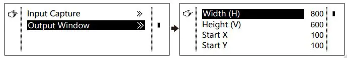
After setting according to the above two steps, the captured contents will only be LT input and displayed at the set area on the LED display, as shown below:
Image Mosaic
When the display screen is huge, two or more VX4U need to be cascaded for loading the huge screen;Choose the method of Image Mosaic: Equal Division, Unequal Division.
- Equal Division: Each VX4U has same load area. It is only required to set total pixel points, rows ,columns of the big screen and the serial No. of each VX4U.
- Unequal Division: Each VX4U could have different load area . It is required to set the total pixel points and the load area size as well as load area staring position N of each VX4U.
Image Mosaic example: The total number of pixels of LED display is 3000×1000, exceeding the load capacity of single VX4U. Two sets of VX4U are used for Image Mosaic XI’A processing. The connection method is shown in the right figure.
Please choose Equal Division or Unequal Division while setting detailed parameters. L The specific parameter settings are shown in the following tables.


Advanced Settings
Several setting options of main functions are included in advanced settings, as A shown in the figure below. Operation of each function will be detailed for users in V the following text.

PIP
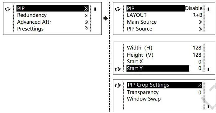
Enable or disable PIP. Set the input source of main screen and PIP, as well as parameters of PIP.
LAYOUT: The position of PIP relative to main screen, including eight types of layouts such as Custom, Left Top, Left Bottom, Right Top, etc. When any type except Custom is selected, the values of horizontal and vertical offset of PIP will be automatically C adjusted to the corresponding values of the selected layout . The meaning of each TE layout type is introduced below:
- Custom refers to that the size and position of PIP need to be set.
- Left Top, Left Bottom, Right Top, Right Bottom, Center refer to that PIP overlaps A with the top-left corner, bottom-left corner, top-right corner, bottom- right T corner and center of main screen.
- Top Bottom, Left Right refer to that main screen and PIP are distributed from top A to bottom or left to right.
Main source/PIP source: Input source switching of main picture and PIP is the same N as the role of input source switching on the front panel.Horizontal Res: Horizontal offset of PIPVertical Res: Vertical offset of PIPHorizontal X: Horizontal width of PIPVertical Y: Vertical height of PIP
PIP Crop Settings: Picture is cropped from the set starting position and is displayed on PIP and its size is set horizontal width and vertical height.Enable this function and then set horizontal width, vertical height, horizontal X and vertical Y.
Transparency: The transparency of PIPWindow Swap: Swap play content of main screen and PIP.
- √ denotes the input sources can be used by both the main screen and PIP at the same time.
- × denotes the input sources cannot be used by both the main screen and PIP at the same time.
- – denotes the main screen and PIP use the same input source.
RedundancyR Set this controller as primary or backup mode.
Advanced Attribute

- VGA Auto ADJ: Sampling parameters of VGA input signal are automatically N adjusted so that the VGA picture is clear and complete. Select this menu and then press the knob once and perform VGA automatic adjustment once. (VGA1 N does not support this feature)
- ADC Calibration: Processors without ADC calibration may cause abnormalities Such as color cast or picture dark while accessing analog signal. VX4U can automatically perform ADC calibration based on input analog signal (including CVBS and VGA) to solve the problems above. Select this menu and then press the knob once and perform ADC calibration once.
- Video Synchronization: Enable the input and output to be synchronous.
- Go Homepage(s): The time period during which the system stops at current interface and then automatically returns to home screen if there is no operation. It defaults to 60s.
Presetting’sSave current configuration parameters as Presetting’s. The Presetting’s can be directly loaded next time, and 10 Presetting’s are saved by default.
Fn SettingsCustomize the function of Fn button, including Black Out, Freeze, VGA Auto ADJ, Video Synchronization. Press Fn and the corresponding function will kick in.
Audio SettingsEnable/disable audio function and control volume and audio mode. D For example, when using the audios input via Audio In port, it is required to enable T audio function first and then set audio mode to fixed. When using the audio from L HDMI, set audio mode to accompanied after enabling audio function and then ., switch source to HDMI. Now the audios we hear come from HDMI.
Display Control
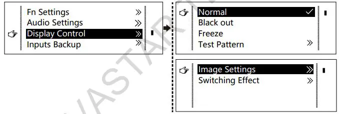
- Normal: Normally display.
- Black Out: The display is blank
- Freeze: The current screen is frozen.
- Test Pattern: There are eight types of test patterns in total, including pure color and lines.
- Image Settings: Contrast, Saturation, Hue, Color Temperature, Red, Green, Blue And Gamma value can be set as required. After they are adjusted to satisfaction, the parameters should be saved.
- Switching Effect: Set the effect when switching screens, including Quick switch, Fade, Shrink Center, Shrink Left Top, Zoom Center, Zoom Left Top and turning off. After selecting the desired effect, it will take effect after pressing the knob.
Tip: When PIP function is enabled, the switching effect will automatically disabled. Only when PIP function is disabled, the special effects of channel switching can take effect.
Inputs BackupSpecify the backup of input source. It will switch to backup source automatically if the signal of input source has faults, which makes it more reliable.
HDMI →DP denotes that DP has been set as the backup of HDMI. Main input L source(unable to be changed) is in left side of the arrow while backup(able to be ., changed) is in the right side. Both main input source and backup can be customized in Custom mode.
Output Resolution
This function can be used to set the output resolution of monitoring. Users can set the function according to actual use and choose either Reset Resolution or Custom.
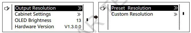
Cabinet Settings
Load Cabinet FilesN VX4U is connected with PC. Run Novato-Mars on PC and import the cabinet I’A configuration files saved before into the controller.
1) Save cabinet configuration files.After receiving card is configured, click ![]() and save cabinet configuration files (.tcfg) to local file on PC.
and save cabinet configuration files (.tcfg) to local file on PC.
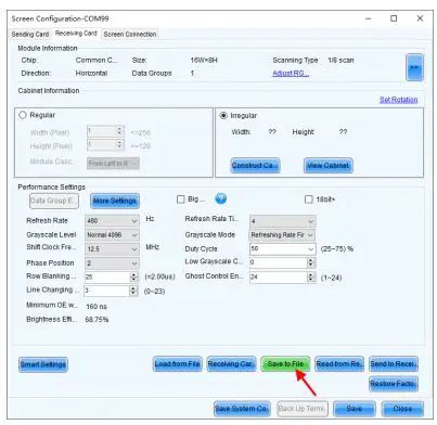
2 ) Import cabinet configuration file into VX4U.
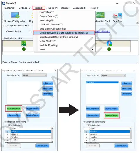
3 ) Load RCFG Files.
Save to RV CardAll current configurations related the receiving card of VX4U are saved into receiving card and will not be lost after power fault.
OLED BrightnessAdjust the gray scale of OLED display.
Hardware VersionCheck the hardware version of VX4U. If new version has been published, LCT-Mars can be connected via PC and the hardware program of VX4U can be upgraded.
Factory Reset
Reset to factory default settings.
Communication Settings
Set the communication mode and network parameters of VX4U. T The communication modes include USB priority and LAN (Local Area Network) L priority. When VX4U is connected to USB and Ethernet control interfaces ., simultaneously, USB control will be used if it is set to USB priority, otherwise, LAN O control will be used if it is set to LAN priority. C Network parameters can be set both manually and automatically. Ensure that the IP address is not conflict with other devices when setting parameter manually.
Language
Switch Language.
8 Specifications
9 FAQs
report this ad
[xyz-ips snippet=”download-snippet”]