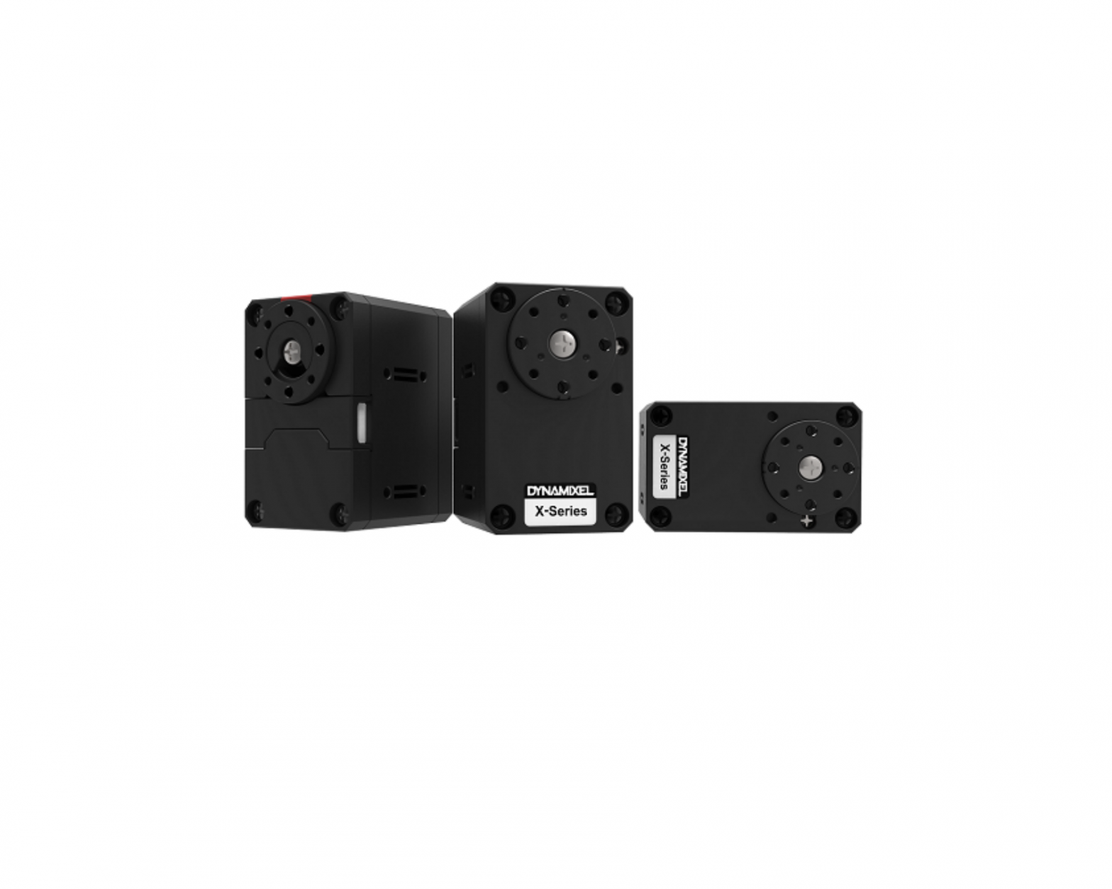
ROBOTIS Dynamixel Servo Motor
H/W Specification
- MCU : ST CORTEX-M3 ( STM32F103C8 @ 72MHZ,32BIT)
- POSITION SENSOR : Contactless absolute encoder (12BIT,360 DEGREE)
- Motor : Cored
- Baud Rate : 9600 bps ~ 4.5 Mbps
- Control Algorithm : PID CONTROL
- Degree of Precision : 0.088°Operating ModesVelocity Control ModePosition Control Mode (0° ~ 360°)Extended Position Control Mode(Multi-turn)PWM Control Mode(Voltage Control Mode)
- Weight : 57.2g
- Dimensions(W x H x D) : 28.5mm x 46.5mm x 34mm
- Gear Ratio : 258.5 : 1
- Stall Torque○ 1.0N.m (at 9.0V, 1.0A)○ 1.4N.m (at 11.1V, 1.3A)○ 1.5N.m (at 12.0V, 1.4A)
- No load speed○ 47rpm (at 9.0V)○ 57rpm (at 11.1V)○ 61rpm (at 12.0V)
- Operating Temperature : -5℃ ~ +72℃
- Input Voltage : 6.5 ~ 12.0V (Recommended : 11.1V)
- Command Signal : Digital Packet
- Protocol Type○ Half duplex Asynchronous Serial Communication (8bit,1stop, No Parity)
- Link (Physical)○ TTL Level Multi Drop Bus
- ID : 253 ID (0~252)
- Feedback : Position, Velocity, Load, Realtime tick, Trajectory, Temperature,
- Input Voltage, etc.
- Material : Engineering Plastic
- Standby current : 52 mA

| The max torque measurement method for the Stall Torque and Performance Graph is different. Stall torque is measured from the max torque that it can reach. This is generally how RC servos measure their torque. For the Performance graph with the N-T curves, it is measured with the load gradually increasing. The motor operation environment is closer to the performance graph, not stall torque method. This is probably why the performance graph is being broadly used in the industrial market. This is why the max torque of the performance grap can actually be less than the stall torque. |
| Precautions when connecting to power supply!– For the stable power supply, we recommend using ROBOTIS controller or SMPS2Dynamixel.– Connect your DYNAMIXEL to power supply while it’s off and turn on/off with the power switch. |
Control Table
The Control Table is a structure of data implemented in the Dynamixel. Users can read a specific Data to get status of the Dynamixel with Read Instruction Packets, and modify Data as well to control Dynamixels with WRITE Instruction Packets.
Control Table, Data, AddressThe Control Table is a structure that consists of multiple Data fields to store status of the Dynamixel or to control the Dynamixel. Users can check current status of the Dynamixel by reading a specific Data from the Control Table with Read Instruction Packets. WRITE Instruction Packets enable users to control the Dynamixel by changing specific Data in the Control Table. The Address is a unique value when accessing a specific Data in the Control Table with Instruction Packets. In order to read or write data, users must designate a specific Address in the Instruction Packet. Please refer to the Protocol section of e-Manual for more details about Packets
| Note : Two’s complement rule is followed to find the negative value.For more information, please refer to the following link (Two’s complement link). |
Area (EEPROM, RAM)
The Control Table is divided into 2 Areas. Data in the RAM Area is reset to initial values when the Dynamixel is turned on (Volatile). On the other hand, modified data in the EEPROM Area keeps their values even when the Dynamixel is turned off (Non-Volatile). Data in the EEPROM Area can only be changed when the value of Torque Enable(64) is cleared to ‘0’.
AccessThe Control Table has two different access properties. ‘RW’ property stands for read and write access permission while ‘R’ stands for read only access permission. Data with the read only property cannot be changed by the WRITE Instruction. Read only property(‘R’) is generally used for measuring and monitoring purpose, and read write property(‘RW’) is used for controlling Dynamixels.
Initial ValueEach data in the Control Table is restored to initial values when the Dynamixel is turned on. Default values in the EEPROM area are initial values of the Dynamixel (factory default settings). If any values in the EEPROM area are modified by a user, modified values will be restored as initial values when the Dynamixels is turned on. Initial Values in the RAM area are restored when the Dynamixels is turned on.
SizeThe Size of data varies from 1 to 4 bytes depend on their usage. Please check the size of data when updating the data with an Instruction Packet.
|
Area |
Address | Size [byte] | Data Name | Description | Access |
initial Value |
| E E P R O M |
0 |
2 | Model Number | Model Number | R |
1060 |
|
2 |
4 | Model Information | Model Information | R |
– |
|
|
6 |
1 |
Version of Firmware | Firmware Version | R | – | |
| 7 | 1 | ID | Dynamixel ID | RW |
1 |
|
|
8 |
1 | Baud Rate | Communication Baud Rate | RW | 1 | |
| 9 | 1 | Return Delay Time | Response Delay Time | RW |
250 |
|
|
10 |
1 | Drive Mode | Drive Mode | RW | 0 | |
| 11 | 1 | Operating Mode | Operating Mode | RW |
3 |
|
|
12 |
1 | Secondary(Shadow) ID | Secondary(Shadow) ID | RW | 255 | |
| 13 | 1 | Protocol Version | Protocol Version | RW |
2 |
|
|
20 |
4 | Homing Offset | Home Position Offset | RW | 0 | |
| 24 | 4 | Moving Threshold | Velocity Threshold for Movement Detection | RW |
10 |
|
|
31 |
1 | Temperature Limit | Maximum Internal Temperature Limit | RW | 72 | |
| 32 | 2 | Max Voltage Limit | Maximum Voltage Limit | RW |
140 |
|
|
34 |
2 | Min Voltage Limit | Minimum Voltage Limit | RW | 60 | |
| 36 | 2 | PWM Limit | Maximum PWM Limit | RW |
885 |
|
|
40 |
4 | Acceleration Limit | Maximum Acceleration Limit | RW | 32767 | |
| 44 | 4 | Velocity Limit | Maximum Velocity Limit | RW |
415 |
|
|
48 |
4 | Max Position Limit | Maximum Position Limit | RW | 4095 | |
| 52 | 4 | Min Position Limit | Minimum Position Limit | RW |
0 |
|
|
63 |
1 | Shutdown | Shutdown Dynamixel | RW | 52 | |
| R A M | 64 | 1 | Torque Enable | Motor Torque On/Off | RW |
0 |
|
65 |
1 | LED | Status LED On/Off | RW | 0 | |
| 68 | 1 | Status Return Level | Select Types of Status Return | RW |
2 |
|
|
69 |
1 | Registered Instruction | Check Reception of Instruction | R | 0 | |
| 70 | 1 | Hardware Error Status | Hardware Error Status | R |
0 |
|
|
76 |
2 | Velocity I Gain | I Gain of Velocity | RW | 1000 | |
| 78 | 2 | Velocity P Gain | P Gain of Velocity | RW |
100 |
|
|
80 |
2 | Position D Gain | D Gain of Position | RW | 4000 | |
| 82 | 2 | Position I Gain | I Gain of Position | RW |
0 |
|
|
84 |
2 | Position P Gain | P Gain of Position | RW | 640 | |
| 88 | 2 | Feedforward 2nd Gain | 2nd Gain of Feed-Forward | RW |
0 |
|
|
90 |
2 | Feedforward 1st Gain | 1st Gain of Feed-Forward | RW | 0 | |
| 98 | 1 | Bus Watchdog | Dynamixel Bus Watchdog | RW |
0 |
|
|
100 |
2 | Goal PWM | Target PWM Value | RW | – | |
| 104 | 4 | Goal Velocity | Target Velocity Value | RW |
– |
|
|
108 |
4 | Profile Acceleration | Acceleration Value of Profile | RW | 0 | |
| 112 | 4 | Profile Velocity | Velocity Value of Profile | RW |
0 |
|
|
116 |
4 | Goal Position | Target Position Value | RW | – | |
| 120 | 2 | Realtime Tick | Count Time in millisecond | R |
– |
|
|
122 |
1 | Moving | Movement Status | R | 0 | |
| 123 | 1 | Moving Status | Detailed Information of Movement Status | R |
0 |
|
|
124 |
2 | Present PWM | Current PWM Value | R | – | |
| 126 | 2 | Present Load | Current Load Value | R |
– |
|
|
128 |
4 | Present Velocity | Current Velocity Value | R | – | |
| 132 | 4 | Present Position | Current Position Value | R |
– |
|
|
136 |
4 | Velocity Trajectory | Target Velocity Trajectory Generated by Profile | R | – | |
| 140 | 4 | Position Trajectory | Target Position Trajectory Generated by Profile | R |
– |
|
|
144 |
2 | Present Input Voltage | Current Input Voltage | R | – | |
| 146 | 1 | Present Temperature | Current Internal Temperature | R |
– |
|
|
168 |
2 | Indirect Address 1 | Indirect Address 1 | RW | 224 | |
| 170 | 2 | Indirect Address 2 | Indirect Address 2 | RW |
225 |
|
|
172 |
2 | Indirect Address 3 | Indirect Address 3 | RW | 226 | |
| … | … | … | … | … |
… |
|
|
218 |
2 | Indirect Address 26 | Indirect Address 26 | RW | 249 | |
| 220 | 2 | Indirect Address 27 | Indirect Address 27 | RW |
250 |
|
|
222 |
2 | Indirect Address 28 | Indirect Address 28 | RW | 251 | |
| 224 | 1 | Indirect Data 1 | Indirect Data 1 | RW |
0 |
|
|
225 |
1 | Indirect Data 2 | Indirect Data 2 | RW | 0 | |
| 226 | 1 | Indirect Data 3 | Indirect Data 3 | RW |
0 |
|
|
… |
… | … | … | … | … | |
| 249 | 1 | Indirect Data 26 | Indirect Data 26 | RW |
0 |
|
|
250 |
1 | Indirect Data 27 | Indirect Data 27 | RW | 0 | |
| 251 | 1 | Indirect Data 28 | Indirect Data 28 | RW |
0 |
|
|
578 |
2 | Indirect Address 29 | Indirect Address 29 | RW | 634 | |
| 580 | 2 | Indirect Address 30 | Indirect Address 30 | RW |
635 |
|
|
582 |
2 | Indirect Address 31 | Indirect Address 31 | RW | 636 | |
| … | … | … | … | … |
… |
|
|
628 |
2 | Indirect Address 54 | Indirect Address 54 | RW | 659 | |
| 630 | 2 | Indirect Address 55 | Indirect Address 55 | RW |
660 |
|
|
632 |
2 | Indirect Address 56 | Indirect Address 56 | RW | 661 | |
| 634 | 1 | Indirect Data 29 | Indirect Data 29 | RW |
0 |
|
|
635 |
1 | Indirect Data 30 | Indirect Data 30 | RW | 0 | |
| 636 | 1 | Indirect Data 31 | Indirect Data 31 | RW |
0 |
|
|
… |
… | … | … | … | … | |
| 659 | 1 | Indirect Data 54 | Indirect Data 54 | RW |
0 |
|
|
660 |
1 | Indirect Data 55 | Indirect Data 55 | RW | 0 | |
| 661 | 1 | Indirect Data 56 | Indirect Data 56 | RW |
0 |
| Note: Protocol 1.0 does not support addresses greater than 256. Therefore, Indirect Address 29 ~ 56 and Indirect Data 29 ~ 56 can only be accessed with Protocol 2.0. |
Address Description
EEPROM Area
Model Number (0)This address stores model number of the Dynamixel.
Firmware Version (6)This address stores firmware version of the Dynamixel.
ID (7)The ID is a unique value in the network to identify each Dynamixel with an Instruction Packet.0~252 (0xFC) values can be used as an ID, and 254(0xFE) is occupied as a broadcast ID. The Broadcast ID(254, 0xFE) can send an Instruction Packet to all connected Dynamixels simultaneously
| Note : Please avoid using an identical ID for multiple Dynamixels. In order to change the ID in the EEPROM Area, Torque Enable(64) has to be cleared to ‘0’ in advance. |
Baud Rate (8)Baud Rate determines serial communication speed between a controller and Dynamixels.
|
Baud Rate |
Baud Rate[bps] |
Margin of Error |
|
0 |
9,600 |
0.000% |
|
1(Default) |
57,600 |
0.000% |
|
2 |
115,200 |
0.000% |
|
3 |
1M |
0.000% |
|
4 |
2M |
0.000% |
|
5 |
3M |
0.000% |
|
6 |
4M |
0.000% |
|
7 |
4.5M |
0.000% |
| Note : Less than 3% of the baud rate error margin will not affect to UART communication |
Return Delay Time (9)After the Dynamixel receives an Instruction Packet, it delays transmitting the Status Packet for Return Delay Time (9). For instance, if the Return Delay Time(9) is set to ‘10’, the Status Packet will be returned after 20[μsec] when the Instruction Packet is received.
| Values |
Description |
|
|
Unit |
2[μsec] |
– |
|
Range |
0 ~ 254 |
Default value ‘250’(500[μsec]), Maximum 508[μsec] |
Drive Mode (10, Available after Firmware version 38)
|
Drive Mode |
Definition |
Values |
|
|
Bit 7 |
0x80 | – | Unused, always ‘0’ |
| Bit 6 | 0x40 | – |
Unused, always ‘0’ |
|
Bit 5 |
0x20 | – | Unused, always ‘0’ |
| Bit 4 | 0x10 | – |
Unused, always ‘0’ |
|
Bit 3 |
0x08 | – | Unused, always ‘0’ |
| Bit 2 | 0x04 | – |
Unused, always ‘0’ |
|
Bit 1 |
0x02 | – |
Unused, always ‘0’ |
|
Bit 0 |
0x01 | Direction of rotation |
Normal mode(‘0’) : CCW(Positive), CW(Negative)Reverse mode(’1’) : CCW(Negative), CW(Positive) |
Operating Mode (11)
|
Operating Mode |
Operating Mode |
Description |
|
1 |
Velocity Control Mode(0° ~ 360°) | This mode controls velocity.This mode is identical to the Wheel Mode(endless) from existing Dynamixels. This mode is ideal for wheel-type robots. |
|
3(Default) |
Position Control Mode | This mode controls position.This mode is identical to the Joint Mode from existing Dynamixels. Operating position range is limited by Max Position Limit(48) and Min Position Limit(52). This mode is ideal for articulated robots that each joint rotates less than 360 degrees. |
|
4 |
Extended Position Control Mode(Multi-turn) | This mode controls position.This mode is identical to the Multi-Turn Mode from existing Dynamixels. 512 turns are supported(-256[rev] ~ 256[rev]). This mode is ideal for multi-turn wrists or conveyer systems or a system that requires an additional reduction gear. |
|
16 |
PWM Control Mode(Voltage Control Mode) | This mode directly controls PWM output. (Voltage Control Mode) |
| Note 1: Switching Operating Mode will reset gains(PID, Feedfoward) properly to the selected Operating Mode. The profile generator and limits will also be reset.① Profile Velocity(112), Profile Acceleration(108) : Reset to ‘0’② Goal PWM(100) : Reset to PWM Limit(36)Note 2: PWM is the abbreviation for Pulse Width Modulation that modulates PWM Duty to control motors. The PWM Control Mode changes pulse width to control average supply voltage to the motor and this technique is widely used in the motor control field. Therefore, PWM Control Mode uses Goal PWM(100) value to control supply voltage for Dynamixel. PWM Control Mode is similar to the Wheel Mode of Dynamixel AX and RX series. |
Secondary(Shadow) ID (12)Set the Dynamixel’s Secondary ID. Secondary ID(12) is a value to identify each Dynamixel, just like ID(7).However, unlike ID(7), Secondary ID(12) is not a unique value. Therefore, Dynamixels with the same Secondary ID value form a group. The differences between Secondary ID(12) and ID(7) are as follows :① Secondary ID(12) is not a unique value. i.e., a lot of Dynamixels may have the same Secondary ID value.② ID(7) has a higher priority than Secondary ID(12). i.e., if Secondary ID(12) and ID(7) are the same, ID(7) will be applied first.③ The EEPROM area of the Control Table cannot be modified with Secondary ID(12). Only the RAM area can be modified.④ If Instruction Packet ID is the same as Secondary ID(12), the Status Packet will not be returned.⑤ If the value of Secondary ID(12) is 253 or higher, the Secondary ID function is deactivated.
|
Values |
Description |
|
| Range | 0 ~ 252253 ~ 255 | Activate Secondary ID functionDeactivate Secondary ID function, Default value ‘255’ |
The following are examples of operation when there are five Dynamixels with ID (7) set from 1 to 5.
- Set all five Dynamixels’ Secondary ID(12) to ‘5’.
- Send Write Instruction Packet(ID = 1, LED(65) = 1).
- Turn on LED of Dynamixel with ID ‘1’ and return the Status Packet.
- Send Write Instruction Packet(ID = 5, LED(65) = 1).
- Turn on LED on five Dynamixels. However, Status Packet of Dynamixel with ID ‘5’ will be returned.
- Set the Secondary ID(12) of all five Dynamixels to ‘100’.
- Send Write Instruction Packet(ID = 100, LED(65) = 0).
- Turn off LED on five Dynamixels. However, as there is no Dynamixel with ID ‘100’, Status Packet is not returned.
Protocol version (13)Users can select Dynamixel protocol version (1.0 and 2.0). It is recommended to use an identical protocol version for multiple Dynamixels.
|
Protocol Version |
Compatible Dynamixels |
|
|
1 |
1.0 |
AX, DX, RX, MX, EX Series |
|
2(Default) |
2.0 |
MX-28, MX-64, MX-106, Dynamixel-X, Dynamixel-PRO Series |
Homing Offset (20)Users can adjust the Home position by setting Home Offset(20). The Homing Offset value is added to the Present Position(132). Present Position(132) = Actual Position + Homing Offset(20).
| Note : In case of the Position Control Mode(Joint Mode) that rotates less than 360 degrees, any invalid Homing Offset(20) values will be ignored(valid range : -1024 ~ 1024). |
Moving Threshold (24)This value helps to determine whether the Dynamixel is in motion or not. When the absolute value of Present Velocity(128) is greater than the Moving Threshold(24), Moving(122) is set to ‘1’, otherwise it is cleared to ‘0’.
|
Values |
Description |
|
|
Unit |
about 0.229[RPM] |
All speed related Data uses the same unit |
|
Range |
0 ~ 1,023 |
Temperature Limit (31)This value limits operating temperature. When the Present Temperature(146) that indicates internal temperature of Dynamixel is greater than the Temperature Limit(31), the Over Heating Error Bit(0x04) and Hardware Error Bit(0x80) in the Hardware Error Status(70) will be set. If Overheating Error Bit(0x04) is configured in the Shutdown(63), Torque Enable(64) is cleared to ‘0’ and Torque is disabled. For more details, please refer to the Shutdown(63) section.
| Values |
Description |
|
|
Unit |
about 1[℃] |
All temperature related Data uses the same unit |
|
Range |
0 ~ 100 |
– |
Max Voltage Limit (32), Min Voltage Limit (34)These values are maximum and minimum operating voltages. When current input voltage acquired from Present Input Voltage(144) exceeds the range of Max Voltage Limit(32) and Min Voltage Limit(34), Voltage Range Error Bit(0x01) and Hardware Error Bit(0x80) in the Hardware Error Status(70) are set. If Input Voltage Error Bit(0x10) is configured in the Shutdown(63), Torque Enable(64) is cleared to ‘0’ and Torque is disabled. For more details, please refer to the Shutdown(63) section.
| Values |
Description |
|
|
Unit |
about 0.1[V] | All voltage related Data uses the same unit |
| Range | 60 ~ 140 |
6.0 ~ 14.0[V] |
PWM Limit (36)This value indicates maximum PWM output. Goal PWM(100) can’t be configured with any values exceeding PWM Limit(36). PWM Limit(36) is commonly used in all operating mode as an output limit, therefore decreasing PWM output will result in decreasing torque and velocity. For more details, please refer to the Gain section of each operating modes.
| Values |
Description |
|
|
Range |
0 ~ 885 |
885 = 100[%] output |
Acceleration Limit (40)This value indicates maximum Profile Acceleration(108). Profile Acceleration(108) can’t be configured with any values exceeding Acceleration Limit(40). Profile Acceleration(108) is used in all operating mode except Torque Control Mode in order to generate a target trajectory. For more details, please refer to the Profile Velocity(112).
|
Values |
Description |
|
|
Unit |
214.577[Rev/min2] | All acceleration related Data uses the same unit. |
| Range | 0 ~ 32,767 |
– |
| Note: Bit information of the Error field in the Status Packet is different from protocol 1.0 and protocol 2.0. This manual complies with protocol 2.0. Please refer to the Protocol section of e-Manual for more details about the protocol. |
Velocity Limit (44)
This value indicates maximum velocity of Goal Velocity(104) and Profile Velocity(112). For more details, please refer to the Profile Velocity(112).
| Values | Description | |
| Unit | 0.229[RPM] |
All velocity related Data uses the same unit |
|
Range |
0 ~ 1,023 |
– |
Max Position Limit (48), Min Position Limit (52)These values limit maximum and minimum target positions for Position Control Mode(Joint Mode) within the range of 1 rotation(0~4095). Therefore, Goal Position(116) should be configured within the position limit range. These values are not used in Extended Position Control Mode and Current-based Position Control Mode.
| Values | Description | |
|
Unit |
0.088[deg] |
All position related Data uses the same unit |
| Range | 0 ~ 4095 |
The range is limited by 1 rotation |
| Note : Max Position Limit(48) and Min Position Limit(52) are only used in Position Control Mode with a single turn(Joint Mode). |
Shutdown (63)The Dynamixel can protect itself by detecting dangerous situations that could occur during the operation. Each Bit is inclusively processed with the ‘OR’ logic, therefore, multiple options can be generated. For instance, when ‘0x05’ (binary : 00000101) is defined as Shutdown(63), Dynamixel can detect both Input Voltage Error(binary : 00000001) and Overheating Error(binary : 00000100). If those errors are detected, Torque Enable(64) is cleared to ‘0’ and the motor output becomes 0[%]. REBOOT is the only method to reset Torque Enable(64) to ‘1’(Torque ON) after the shutdown. The followings are detectable situations
|
Shutdown |
Definition |
Description |
|
|
bit 7 |
0x80 | – | Unused, always ‘0’ |
|
bit 6 |
0x40 | – | Unused, always ‘0’ |
|
bit 5 |
0x20 | Overload Error(Default) | Detect persistent load that exceeds maximum output |
|
bit 4 |
0x10 | Electrical Shock Error(Default) | Detect electrical shock on the circuit, or input power is insufficient to operate the motor |
|
bit 3 |
0x08 | Motor Encoder Error | Detect malfunction of the motor encoder |
|
bit 2 |
0x04 | Overheating Error(Default) | Detect internal temperature exceeds the configured operating temperature |
|
bit 1 |
0x02 | – | Unused, always ‘0’ |
|
bit 0 |
0x01 | Input Voltage Error | Detect input voltage exceeds the configured operating voltage |
Note : If Shutdown occurs, use below method to REBOOT Dynamixels.
|
RAM Area
Torque Enable (64)Controls Torque ON/OFF. Writing ‘1’ to this address will turn on the Torque and all Data in the EEPROM area will be protected
|
Values |
Description |
|
0(Default) |
Torque OFF(Free-run) and the motor does not generate torque. |
|
1 |
Torque ON and all Data in the EEPROM area will be locked. |
LED (65)Turn on or turn off the LED. Dynamixel LED can only be controlled by LED(65).Values Description
|
Values |
Description |
|
0(Default) |
Turn off the LED. |
|
1 |
Turn on the LED. |
| Note : If the ID of Instruction Packet is set to Broad Cast ID(0xFE), Status Packet will not be returned for READ and WRITE Instructions regardless of Status Return Level(68). For more details, please refer to the Protocol section of e-Manual. |
Registered Instruction (69)This value will be set to ‘1’ when Dynamixel receives REG_WRITE Instruction Packet and processing ACTION Instruction Packet will clear the value to ‘0’.
Hardware Error Status (70)This value indicates hardware error status. For more details, please refer to the Shutdown(63).
Velocity I Gain (76), Velocity P Gain (78)These values indicate Gains of Velocity Control Mode. Gains of Dynamixel’s internal controller can be calculated from Gains of the Control Table as shown below. The constant in each equations include sampling time. Velocity P Gain of Dynamixel’s internal controller is abbreviated to KVP and that of the Control Table is abbreviated to KVP(TBL)
|
Controller Gain |
Conversion Equations | Range |
Description |
|
|
Velocity I Gain(76) |
KVI | KVI = KVI(TBL) / 65563 | 0 ~ 16383 |
I Gain |
|
Velocity P Gain(78) |
KVP | KVP = KVP(TBL) / 128 | 0 ~ 16383 |
P Gain |
Below figure is a block diagram describing the velocity controller in Velocity Control Mode. When the instruction transmitted from the user is received by Dynamixel, it takes following steps until driving the horn
- An Instruction from the user is transmitted via Dynamixel bus, then registered to Goal Velocity(104).
- Goal Velocity(104) is converted to target velocity trajectory by Profile Acceleration(108).
- The target velocity trajectory is stored at Velocity Trajectory(136).
- PI controller calculates PWM output for the motor based on the target velocity trajectory.
- Goal PWM(100) sets a limit on the calculated PWM output and decides the final PWM value.
- The final PWM value is applied to the motor through an Inverter, and the horn of Dynamixel is driven.
- Results are stored at Present Position(132), Present Velocity(128), Present PWM(124) and Present Load(126).

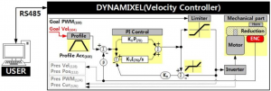
| Note: Ka stands for Anti-windup Gain and ‘β’ is a conversion coefficient of position and velocity that cannot be modified by users. For more details about the PID controller, please refer to the below website. http://en.wikipedia.org/wiki/PID_controller |
Position D Gain (80), Position I Gain (82), Position P Gain (84)Feedforward 2nd Gain (88), Feedforward 1st Gain (90)These Gains are used in Position Control Mode and Extended Position Control Mode. Gains of Dynamixel’s internal controller can be calculated from Gains of the Control Table as shown below. The constant in each equations include sampling time. Position P Gain of Dynamixel’s internal controller is abbreviated to KPP and that of the Control Table is abbreviated to KPP(TBL)
|
Controller Gain |
Conversion Equation | Range | Description | |
|
Position D Gain(80) |
KPD |
KPD = KPD(TBL) / 16 |
0 ~ 16383 |
D Gain |
|
Position I Gain(82) |
KPI |
KPI = KPI(TBL) / 65536 |
0 ~ 16383 |
I Gain |
|
Position P Gain(84) |
KPP |
KPP = KPP(TBL) / 128 |
0 ~ 16383 |
P Gain |
|
Feedforward 2nd Gain(88) |
KFF2nd |
KFF2nd = KFF2nd(TBL) / 4 |
0 ~ 16383 |
Feedforward Acceleration Gain |
|
Feedforward 1st Gain(90) |
KFF1st |
KFF1st = KFF1st(TBL) / 4 |
0 ~ 16383 |
Feedforward Velocity Gain |
Below figure is a block diagram describing the position controller in Position Control Mode and Extended Position Control Mode. When the instruction from the user is received by Dynamixel, it takes following steps until driving the horn.
- An Instruction from the user is transmitted via Dynamixel bus, then registered to Goal Position(116).
- Goal Position(116) is converted to target position trajectory and target velocity trajectory by Profile Velocity(112) and Profile Acceleration(108).
- The target position trajectory and target velocity trajectory is stored at Position Trajectory(140) and Velocity Trajectory(136) respectively.
- Feedforward and PID controller calculate PWM output for the motor based on target trajectories.
- Goal PWM(100) sets a limit on the calculated PWM output and decides the final PWM value.
- The final PWM value is applied to the motor through an Inverter, and the horn of Dynamixel is driven.
- Results are stored at Present Position(132), Present Velocity(128), Present PWM(124) and Present Load(126).
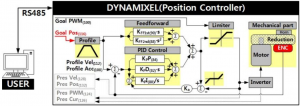
| Note1): In case of PWM Control Mode, both PID controller and Feedforward controller are deactivated while Goal PWM(100) value is directly controlling the motor through an Inverter. In this manner, users can directly control the supplying voltage to the motor. |
| Note2) : Ka is an Anti-windup Gain that cannot be modified by users. For more details about the PID controller and Feedforward controller, please refer to the below websites. http://en.wikipedia.org/wiki/PID_controller https://en.wikipedia.org/wiki/Feed_forward_(control) |
Bus Watchdog (98, Available after Firmware version 38)Bus Watchdog (98) is a safety device (Fail-safe) that stops the Dynamixel if the communication between the controller and Dynamixel communication (RS485, TTL) is disconnected due to an unspecified error.Communication is defined as all the Instruction Packet in the Dynamixel Protocol.
|
Values |
Description |
|
|
Unit |
20[ms] |
|
|
Range |
0 |
Deactivate Bus Watchdog Function, Clear Bus Watchdog Error |
|
1 ~ 127 |
Activate Bus Watchdog | |
|
-1 |
Bus Watchdog Error Status |
The Bus Watchdog function monitors the communication interval (time) between the controller and Dynamixel when Torque Enable (64) is ‘1’.If the measured communication interval (time) is larger than Bus Watchdog (98), the Dynamixel will be stopped. Bus Watchdog (98) will be changed to ‘-1’ (Bus Watchdog Error).If the Bus Watchdog Error screen appears, the Goal Value (Goal PWM(100), Goal Current(102), Goal Velocity(104), Goal Position(116)) will be changed to read-only property.Therefore, when a new value is written to the Goal Value, a Range Error will be returned via the Status packet.If the value of Bus Watchdog (98) is changed to ‘0’, Bus Watchdog Error will be cleared
| Note: For details of Range Error, please refer to the protocol of the e-Manual. |
The following are examples of the operation of the Bus Watchdog function.
- After setting the operating mode (11) to speed control mode, change the Torque Enable (64) to ‘1’.
- If ’50’ is written in the Goal Velocity (104), the Dynamixel will rotate in CCW direction.
- Change the value of Bus Watchdog (98) to ‘100’ (2,000 [ms]). (Activate Bus Watchdog Function)
- If no instruction packet is received for 2,000 [ms], the Dynamixel will stop. When it stops, the Profile Acceleration (108) and Profile Velocity (112) are applied as ‘0’.
- The value of Bus Watchdog (98) changes to ‘-1’ (Bus Watchdog Error). At this time, the access to the Goal Value will be changed to read-only.
- If ‘150’ is written to the Goal Velocity (104), Range Error will be returned via Status Packet.
- If the value of Bus Watchdog (98) is changed to ‘0’, Bus Watchdog Error will be cleared.
- If “150” is written in the Goal Velocity (104), the Dynamixel will rotate in CCW direction.
Goal PWM (100)In case of PWM Control Mode, both PID controller and Feedforward controller are deactivated while Goal PWM(100) value is directly controlling the motor through an Inverter. In other control modes, this value is used to limit PWM value. This value cannot exceed PWM Limit(36).Please refer to the Gain section in order to see how Goal PWM(100) affects to different control modes.
|
Values |
Description |
|
|
Range |
-PWM Limit(36) ~ PWM Limit(36) |
Initial Value of PWM Limit(36) : ‘885’ |
Goal Velocity (104)In case of Velocity Control Mode, Goal Velocity(104) can be used to set a target velocity. This value cannot exceed Velocity Limit(44). For now, Goal Velocity(104) is used for target velocity, but this value is not used to limit the velocity.
|
Values |
Description |
|
|
Unit |
0.229[RPM] |
All velocity related Data uses the same unit |
|
Range |
-Velocity Limit(44) ~ Velocity Limit(44) |
– |
| Note1): The maximum velocity and maximum torque of Dynamixel is affected by supplying voltage. Therefore, if supplying voltage changes, so does the maximum velocity. This manual complies with recommended supply voltage.Note2): If Profile Acceleration(108) and Goal Velocity(104) are modified simultaneously, modified Profile Acceleration(108) will be used to process Goal Velocity(104). |
Profile Acceleration (108)The acceleration of Profile can be set with this value. Profile Acceleration(108) can be used in all control modes except Torque Control Mode. Profile Acceleration(108) cannot exceed Acceleration Limit(40). For more details, please refer to the Profile Velocity(112).
| Values | Description | |
|
Unit |
214.577[Rev/min2] |
All acceleration related Data uses the same unit, |
|
Range |
0 ~ Acceleration Limit(40) |
The value ‘0’ on Profile Acceleration(108) means infinite acceleration. |
Profile Velocity (112)The Maximum velocity of Profile can be set with this value. Profile Velocity(112) can be used in all control modes except Torque Control Mode and Velocity Control Mode. Profile Velocity(112) cannot exceed Velocity Limit(40). Velocity Control Mode only uses Profile Acceleration(108) instead of Profile Velocity(112)
|
Values |
Description |
|
|
Unit |
0.229[RPM] |
All velocity related Data uses the same unit |
|
Range |
0 ~ Velocity Limit(44) |
If Profile Velocity(112) is set to ‘0’, it stands for infinite velocity. |
The Profile is an acceleration/deceleration control method to reduce vibration, noise and load of the motor by controlling dramatically changing velocity and acceleration. It is also called Velocity Profile as it controls acceleration and deceleration based on velocity. Dynamixel provides 4 different types of Profile. The following explains 4 Profiles and how to select them. Profiles are usually selected by a combination of Profile Velocity(112) and Profile Acceleration(108). Triangular and Trapezoidal Profiles exceptionally consider total travel distance(ΔPos, the distance difference between target position and current position) as an additional factor. For convenience, Profile Velocity(112) is abbreviated to VPRFL and Profile Acceleration(108) is abbreviated to VPRFL. ‘X’ stands for “Don’t Care” case.
When given Goal Position(116), Dynamixel’s profile creates target velocity trajectory based on current velocity(initial velocity of the Profile). When Dynamixel receives updated target position from a new Goal Position(116) while it is moving toward the previous Goal Position(116), velocity smoothly varies for the new target velocity trajectory. Maintaining c velocity continuity while updating target velocity trajectory is called Velocity Override. For a simple calculation, let’s assume that the initial velocity of the Profile is ‘0’. The following explains how Profile processes Goal Position(116) instruction in Position Control mode, Extended Position Control Mode, Current-based Position Control Mode.
- An Instruction from the user is transmitted via Dynamixel bus, then registered to Goal Position(116).
- Acceleration time(t1) is calculated from Profile Velocity(112) and Profile Acceleration(108).
- Types of Profile is decided based on Profile Velocity(112), Profile Acceleration(108) and total travel distance(ΔPos, the distance difference between target position and current position)
Condition
Types of Profile
VPRFL(112) = 0 Profile not used (Step Instruction)
(VPRFL(112) ≠ 0) & (APRF(108) = 0) Rectangular Profile
(VPRFL(112) ≠ 0) & (APRF(108) ≠ 0) & (VPRFL_TRI ≤ VPRFL(112)) Triangular Profile
(VPRFL(112) ≠ 0) & (APRF(108) ≠ 0) & (VPRFL_TRI > VPRFL(112)) Trapezoidal Profile
- Selected Profile type is stored at Moving Status(123).(Refer to the Moving Status(123))
- Dynamixel is driven by the calculated target trajectory from Profile.
- Target velocity trajectory and target position trajectory from Profile are stored at Velocity Trajectory(136) and Position Trajectory(140) respectively.
- VPRFL_TRI of ③ and Travel time(t3) to reach Goal Position(116) is calculated as below.

Note1): Dynamixel supports Jerk control in order to minimize dramatic change of acceleration. Therefore, actual travel time by the target trajectory of Profile could be longer than t3(t4 of above figure).Note2): Velocity Control Mode only uses Profile Acceleration(108). Step and Trapezoidal Profiles are supported. Velocity Override and Jerk control are supported as well. Acceleration time(t1) can be calculated as below equation.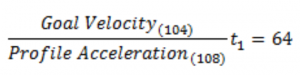 |
Goal Position (116)Target position can be set with Goal Position(116). From the front view of Dynamixels, CCW is an increasing direction whereas CW is a decreasing direction. The way to reaching Goal Position(116) is differ by 4 Profiles provided by Dynamixels. Please refer to the Profile Velocity(112) for more details.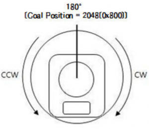
|
Values |
Description |
||
|
Unit |
0.088[deg] |
1[rev] : 0 ~ 4,095 |
|
|
Range |
Position Control Mode |
Min Position Limit(52) ~ Max Position Limit(48) |
Initial Value : 0 ~ 4,095 |
|
Extended Position Control Mode |
-1,048,575 ~ 1,048,575 |
-256[rev] ~ 256[rev] |
Realtime Tick (120)This value indicates Dynamixel’s time.
|
Values |
Description |
|
|
Unit |
1[ms] |
– |
|
Range |
0 ~ 32,767 |
The value resets to ‘0’ when it exceeds 32,767 |
Moving (122)This value indicates whether Dynamixel is in motion or not. If absolute valueof Present Velocity(128) is greater than Moving Threshold(24), Moving(122) is set to ‘1’. Otherwise, it will be cleared to ‘0’.However, this value will always be set to ‘1’ regardless of Present Velocity(128) while Profile is in progress with Goal Position(116) instruction.
|
Moving |
Description |
| 0 | Movement is not detected |
|
1 |
Movement is detected, or Profile is in progress(Goal Position(116) instruction is being processed) |
Moving Status (123)This value provides additional information about the movement. Following Error Bit(0x08) and In-Position Bit(0x01) only work with Position Control Mode, Extended Position Control Mode. This value provides additional information about the movement. Following Error Bit(0x08) and In-Position Bit(0x01) only work with Position Control Mode, Extended Position Control Mode.
|
Moving Status |
Details |
Description |
|
|
Bit 7 |
0x80 |
– |
Unused |
|
Bit 6 |
0x40 |
– |
Unused |
|
Bit 5 ~ Bit 4 |
0x30 |
Profile Type(0x30) |
Trapezoidal Velocity Profile |
|
Profile Type(0x20) |
Triangular Velocity Profile |
||
|
Profile Type(0x10) |
Rectangular Velocity Profile |
||
|
Profile Type(0x00) |
No Profile Used (Step) |
||
|
Bit 3 |
0x08 |
Following Error |
Dynamixel fails to reach target position trajectory |
|
Bit 2 |
0x04 |
– |
Unused |
|
Bit 1 |
0x02 |
Profile Ongoing |
Profile is in progress with Goal Position(116) instruction |
|
Bit 0 |
0x01 |
In-Position |
Dynamixel is reached to target position |
Present PWM (124)This value indicates present PWM. For more details, please refer to the Goal PWM(100).
Present Load (126)This value indicates present Load on the Dynamixel. For example, if Present Load(126) has a value of ‘500’, this means 50[%] of load is being applied to CCW direction.
|
Values |
Description |
|
|
Unit |
0.1[%] |
– |
|
Range |
-1,000 ~ 1,000 |
Positive Value(Load on CCW direction)Negative Value(Load on CW direction) |
| Note: Present Load is not a torque sensor measurement, but a calculated value using internal output value. Therefore, this value might not suitable for measuring weight or torque. It is recommended to use this value to estimate the torque and direction of the torque on the corresponding joint |
Present Velocity (128)This value indicates current Velocity. For more details, please refer to the Goal Velocity(104).
Present Position (132)This value indicates present Position. For more details, please refer to the Goal Position(116)
| Note: Present Position (132) represents 4[byte] continuous range (-2,147,483,648 ~ 2,147,483,647) when Torque is turned off regardless of Operating Mode (11). However, Present Position (132) is reset in those cases:Case 1) Present Position (132) is reset with the value within 1[rev] (0 ~ 4,095) when Operating Mode (11) is changed to Position Control Mode.Case 2) Present Position (132) is reset with the value within 1[rev] (0 ~ 4,095) when Torque is turned on in Position Control Mode. Homing Offset (20) can affect to the Present Position (132) value. |
Velocity Trajectory (136)This is a target velocity trajectory created by Profile. Operating method can be changed based on control mode. For more details, please refer to the Profile Velocity(112).
- Velocity Control Mode : When Profile reaches to the endpoint, Velocity Trajectory(136) becomes equal to Goal Velocity(104).
- Position Control Mode, Extended Position Control Mode, Current-based Position Control Mode : Velocity Trajectory is used to create Position Trajectory(140). When Profile reaches to endpoint, Velocity Trajectory(136) is cleared to ‘0’.
Position Trajectory (140)This is a target position trajectory created by Profile. This value is only used in Position Control Mode, Extended Position Control Mode. For more details, please refer to the Profile Velocity(112).
Present Input Voltage (144)This value indicates current voltage that is being supplied. For more details, please refer to the Max/Min Voltage Limit(32, 34).
Present Temperature (146)This value indicates internal temperature of Dynamixel. For more details, please refer to the Temperature Limit(31).
Indirect Address 1 ~ 28 (168, 170 ~ 220, 222), Indirect Address 29 ~ 56 (578, 580 ~ 630, 632)Indirect Data 1 ~ 28 (224, 225 ~ 250, 251), Indirect Data 29 ~ 56 (634, 635 ~ 660, 661)Indirect Address and Indirect Data are useful when accessing two remote addresses in the Control Table as sequential addresses. Sequential addresses increase Instruction Packet efficiency. Addresses that can be defined as Indirect Address is limited to RAM area(Address 64 ~ 661).If specific address is allocated to Indirect Address, Indirect Address inherits features and properties of the Data from the specific Address. Property includes Size(Byte length), value range, and Access property(Read Only, Read/Write). For instance, allocating 65(Address of LED) to Indirect Address 1(168), Indirect Data 1(224) can perform exactly same as LED(65).
- Example 1) Allocating Size 1[byte] LED(65) to Indirect Data 1(224)A. Indirect Address 1(168) : change the value to ’65’ which is the address of LEDB. Set Indirect Data 1(224) to ‘1’ → LED(65) also becomes ‘1’ and LED is turned on.C. Set Indirect Data 1(224) to ‘0’ → LED(65) also becomes ‘0’ and LED is turned off.
- Example 2) Allocating Size 4[byte] Goal Position(116) to Indirect Data 2 (225), all 4[byte] has to be allocated.A. Indirect Address 2(170) : change the value to ‘116’ which is the first address of Goal Position.B. Indirect Address 3(172) : change the value to ‘117’ which is the first address of Goal Position.C. Indirect Address 4(174) : change the value to ‘118’ which is the first address of Goal Position.D. Indirect Address 5(176) : change the value to ‘119’ which is the first address of Goal Position.E. Set 4[byte] value ‘1024’ to Indirect Data 2 → Goal Position(116) also becomes ‘1024 and Dynamixel moves.
|
Indirect Address |
Values |
Description |
|
Range |
64~661 |
Indirection Address can’t be allocated with EEPROM area |
| Note 1): In order to allocate Data in the Control Table longer than 2[byte] to Indirect Address, all address must be allocated to Indirect Address like the above Example 2.Note 2): Indirect Address 29 ~ 56 and Indirect Data 29 ~ 56 can only be accessed with Protocol 2.0. |
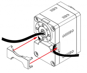
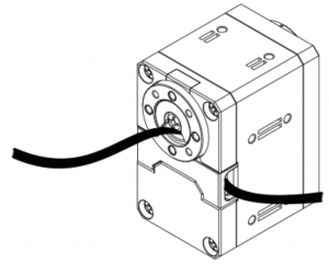
Wiring Instructions through hollow back case
1.
2.
3.
4.
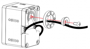 |
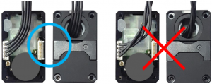
| Caution for Dynamixel X-Series cable assembly through hollow caseOrganize the entangled cable before assembling the back case. Do not assemble the back case with entangled cable. The entangled cable can be squashed by the case and cause communication error. |
Combination
Option Frame Front A
Option Frame Front B
Option Frame Side 1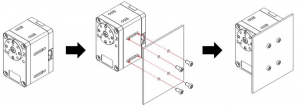
Option Frame Bottom 1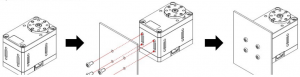

| Taps on each side of the body are self-tapping holes. Be careful not to use these holes repeatedly as it could damage the thread in the hole. |
Dimension

http://support.robotis.com/en/product/actuator/dynamixel_x/xl_series/xl430-w250.htm

References
[xyz-ips snippet=”download-snippet”]