TELTONIKA
Advanced Waterproof TrackerInstruction Manual
Model: FMB202 v1.3
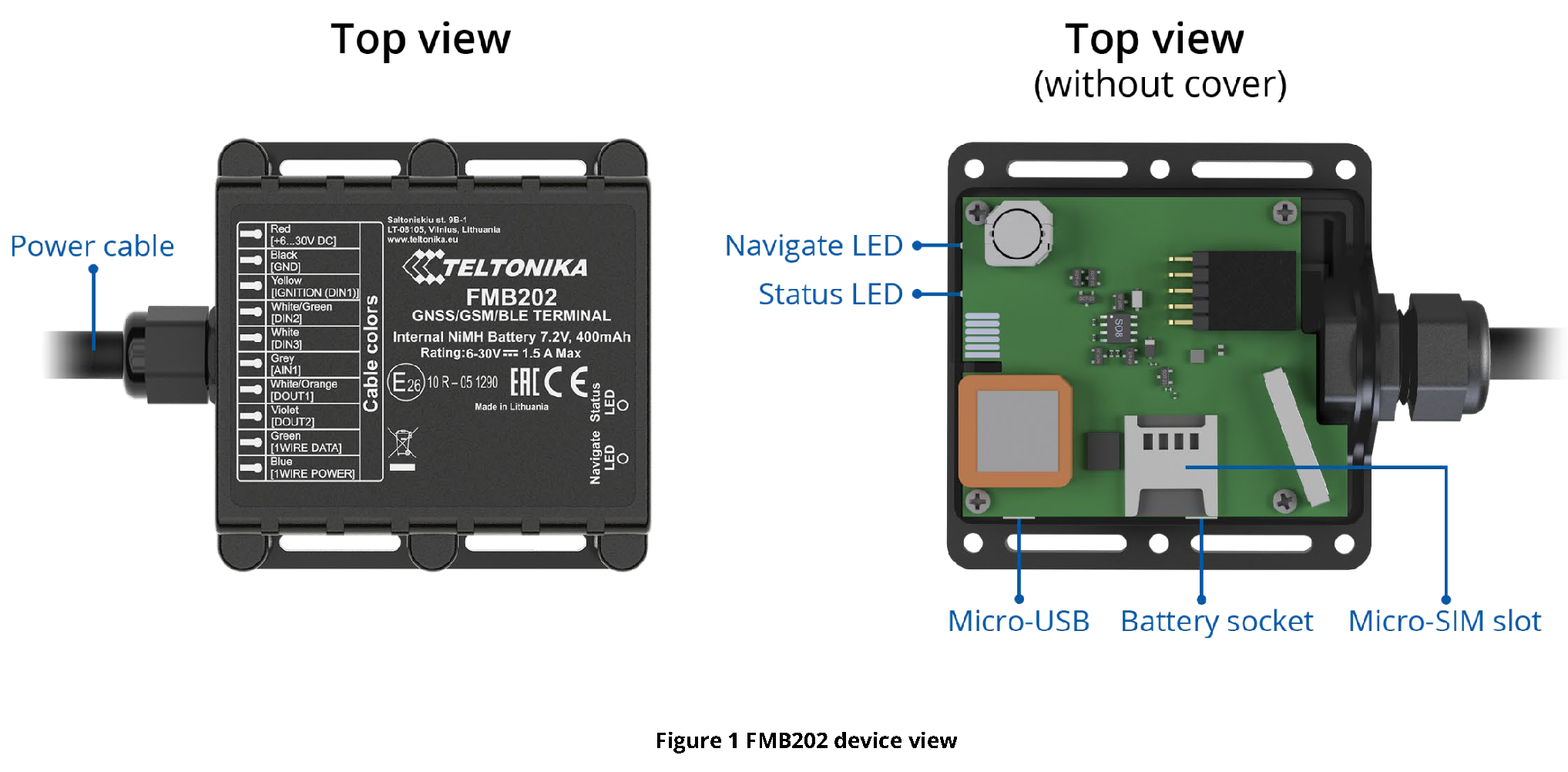
Know your device
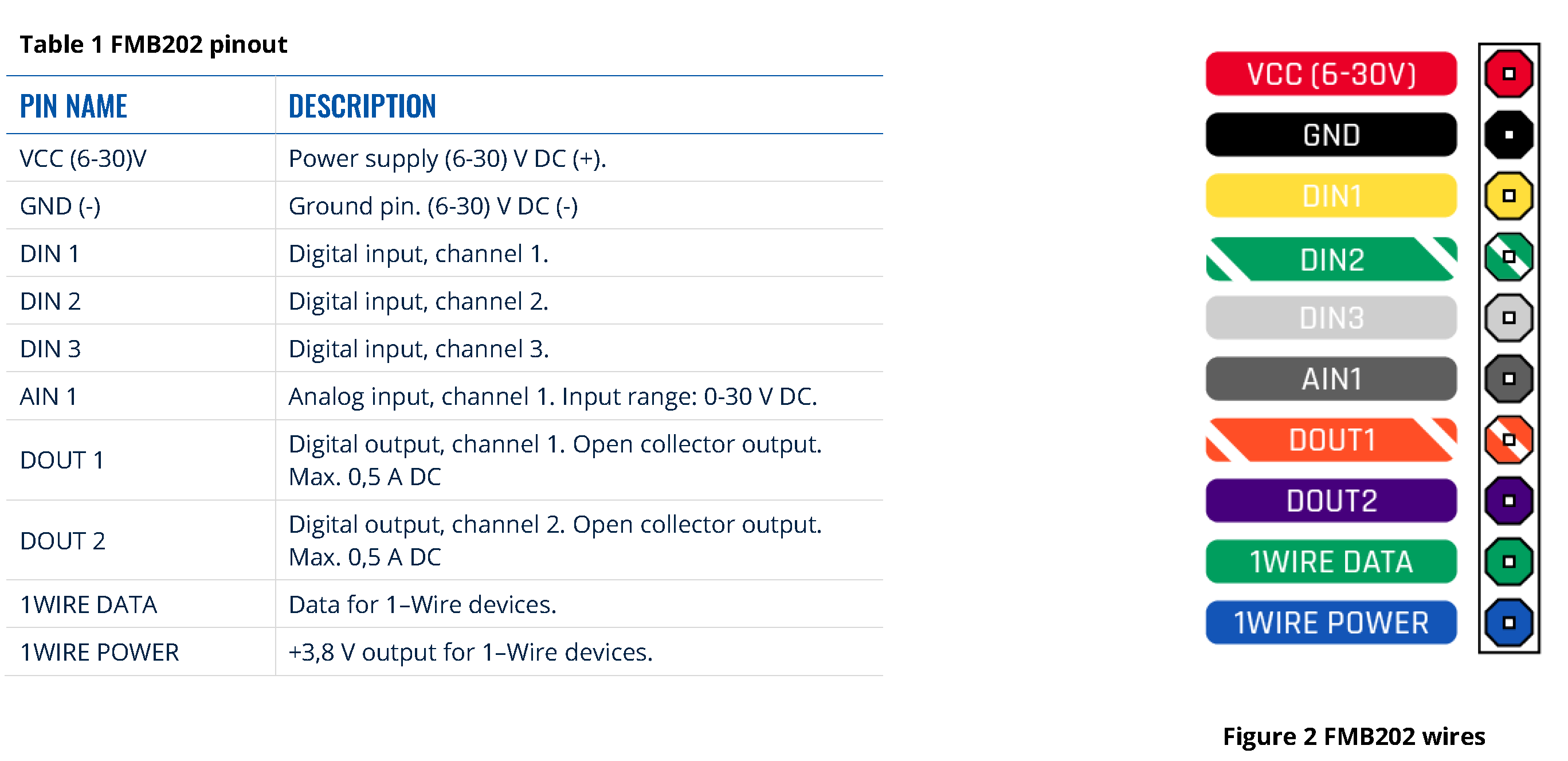
Pinout
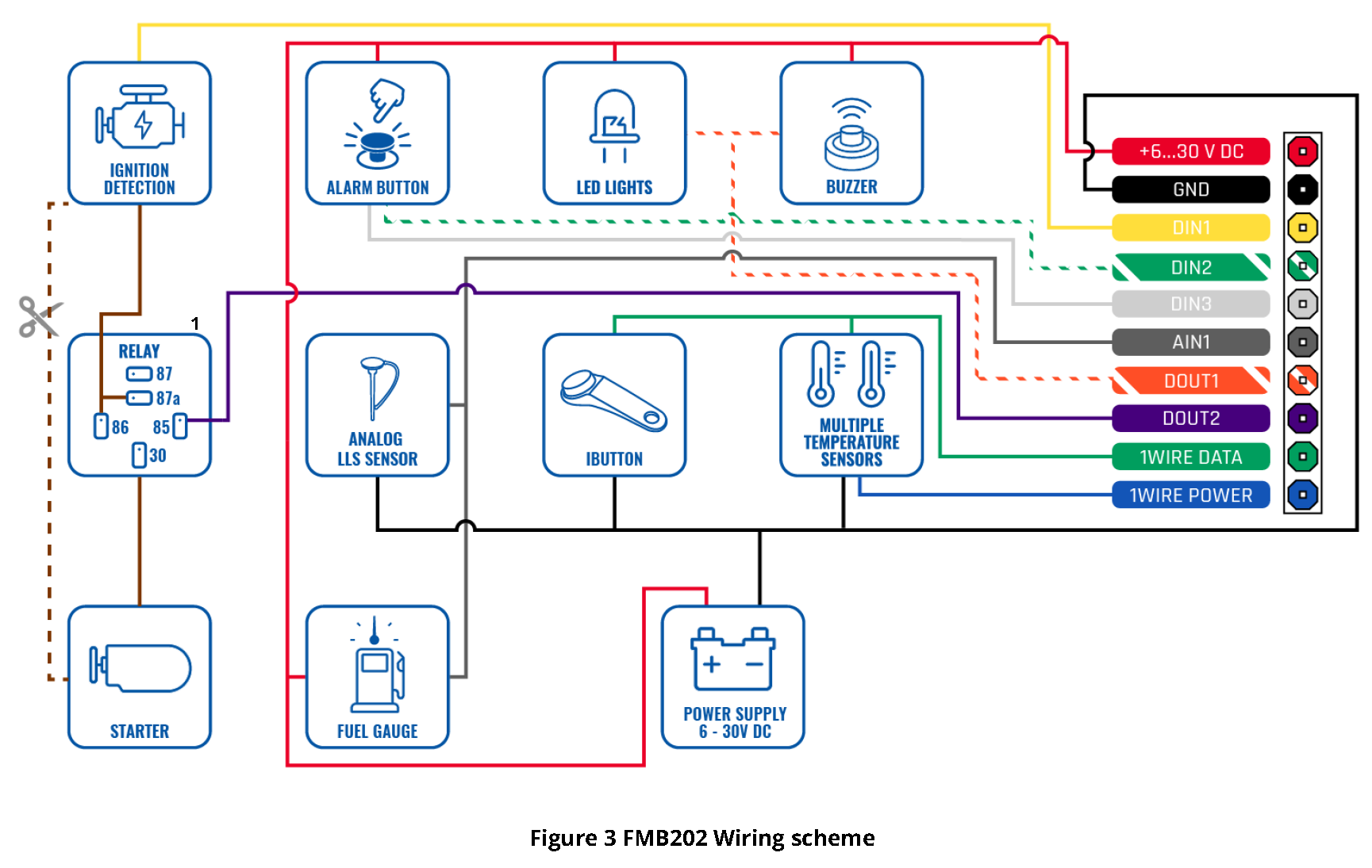
Wiring scheme
Set up your device
How to insert Micro-SIM card and connect the battery
- Unscrew 6 screws counterclockwise that are located on the bottom of the device.
- Remove the cover.
- Insert Micro-SIM card as shown with PIN request disabled or read our Wiki how to enter it later in Teltonika Configurator. Make sure that Micro-SIM card cut-off corner is pointing forward to slot.
- Connect battery as shown to device.
- After configuration, see “PC Connection (Windows)”, attach device cover back and screw in all screws.
- Device is ready to be mounted.

PC Connection (Windows)
- Power-up FMB202 with DC voltage (6 – 30 V) power supply using power cable. LED’s should start blinking, see “LED indications”.
- Connect device to computer using Micro-USB cable or Bluetooth connection:Using Micro-USB cable▬ You will need to install USB drivers, see “How to install USB drivers (Windows)”Using Bluetooth▬ FMB202 Bluetooth is enabled by default. Turn on Bluetooth on your PC, then select Add Bluetooth or other device > Bluetooth. Choose your device named – “FMBxxx_last_7_imei_digits”, without LE in the end. Enter default password 5555, press Connect and then select Done.
- You are now ready to use the device on your computer.
How to install USB drivers (Windows)
- Please download COM port drivers from here.
- Extract and run TeltonikaCOMDriver.exe.
- Click Next in driver installation window.
- In the following window click Install button.
Setup will continue installing the driver and eventually the confirmation window will appear. Click Finish to complete the setup.
Configuration (Windows)At first FMB202 device will have default factory settings set. These settings should be changed according to the user’s needs. Main configuration can be performed via Teltonika Configurator software. Get the latest Configurator version from here. Configurator operates on Microsoft Windows OS and uses prerequisite MS .NET Framework. Make sure you have the correct version installed.
Table 2 MS .NET requirements
MS .NET REQUIREMENTS

Downloaded Configurator will be in compressed archive. Extract it and launch Configurator.exe. After launch software language can be changed by clicking ![]() in the right bottom corner (Figure 10 Language selection).
in the right bottom corner (Figure 10 Language selection).

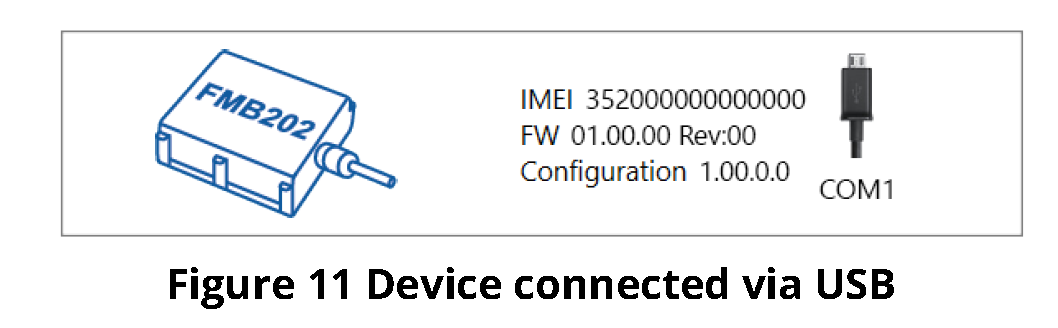
Configuration process begins by pressing on connected device (Figure 11 Device connected via USB).
After connection to Configurator Status window will be displayed
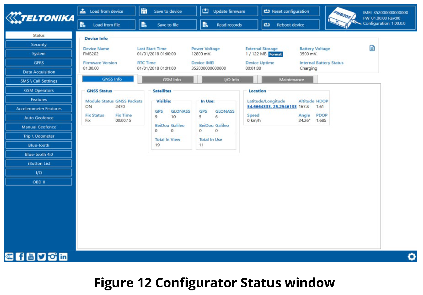
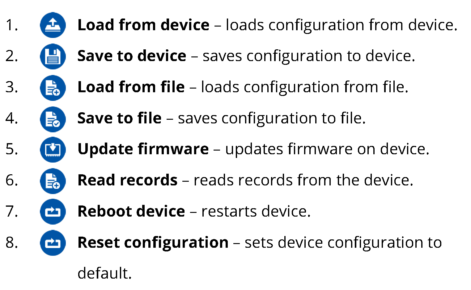
(Figure 12 Configurator Status window).Various Status window tabs display information about GNSS, GSM, I/O, Maintenance and etc. FMB202 has one user editable profile, which can be loaded and saved to the device. After any modification of configuration the changes need to be saved to device using Save to device button. Main buttons offer following functionality:
Most important configurator section is GPRS – where all your server and GPRS settings can be configured and Data Acquisition – where data acquiring parameters can be configured. More details about FMB202 configuration using Configurator can be found in our Wiki.
Quick SMS configuration
Default configuration has optimal parameters present to ensure best performance of track quality and data usage.Quickly set up your device by sending this SMS command to it:

Default configuration settings
After successful SMS configuration, FMB202 device will synchronize time and update records to configured server. Time intervals and default I/O elements can be changed by using Teltonika Configurator or SMS parameters.
Mounting recommendations
Connecting wires
- Wires should be fastened to stable wires or other non-moving parts. Any heat emitting and/or moving objects should be kept away from the wires.
- There should be no exposed wires. If factory isolation was removed while connecting the wires, the isolation material should be applied.
- If the wires are placed in the exterior or in places where they can be damaged or exposed to heat, humidity, dirt, etc., additional isolation should be applied and the wires should not be loose.
- Wires cannot be connected to the board computers or control units.
Connecting power source
- Be sure that after the car computer goes to sleep mode, power might be still available on the power wires. Depending on the car model, this may happen in 5 to 30 minutes period.
- When the module is connected, measure the voltage again to make sure it did not decrease.
- It is recommended to connect to the main power cable in the fuse box.
- 3 A, 125 V external fuse shall be used.
Connecting ignition wire
- Be sure to check if it is a real ignition wire i. e. power does not disappear after starting the engine.
- Check if this is not an ACC wire (when key is in the first position, most of the vehicle electronics are available).
- Check if power is still available when you turn off any of vehicles devices.
- Ignition is connected to the ignition relay output. As alternative, any other relay, which has power output when ignition is on, may be chosen.
Connecting ground wire
- Ground wire is connected to the vehicle frame or metal parts that are fixed to the frame.
- If the wire is fixed with the bolt, the loop must be connected to the end of the wire.
- For better contact scrub paint from the spot where loop is going to be connected.
PAY ATTENTION! Connecting the power supply must be carried out in a very low impedance point of on-board vehicle network. Connecting the GND at an arbitrary point to the mass of the car is unacceptable, as static and dynamic potentials on the line GND will be unpredictable, which can lead to unstable FMB202 operation and even its failure.
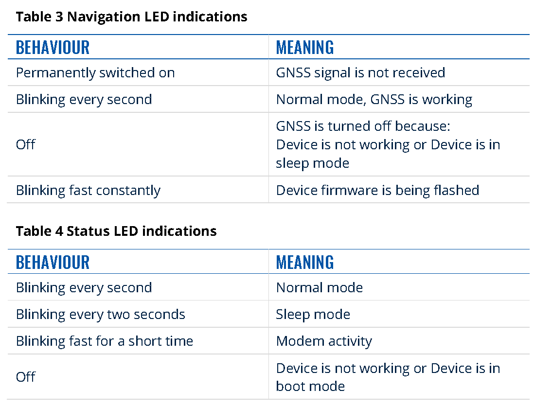
LED indications
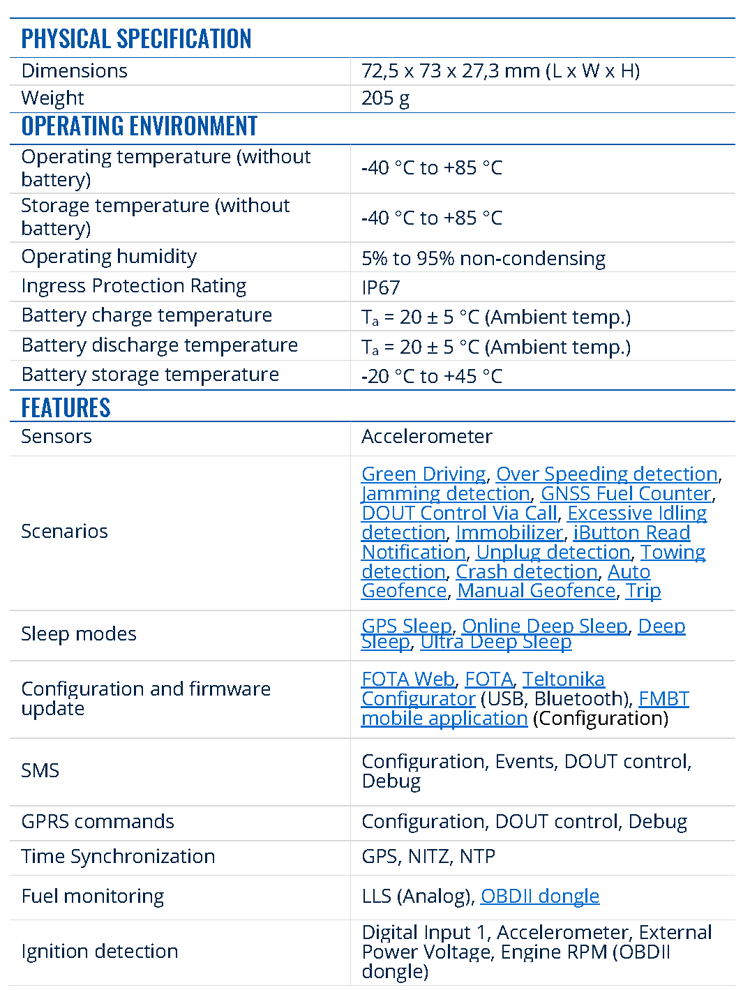
Characteristics
Basic characteristics


Electrical characteristics
Table 6 Electrical characteristics


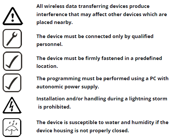
Safety information
This message contains information on how to operate FMB202 safely. By following these requirements and recommendations, you will avoid dangerous situations. You must read these instructions carefully and follow them strictly before operating the device!
- The device uses SELV limited power source. The nominal voltage is +12 V DC. The allowed voltage range is +6..+30 V DC.
- To avoid mechanical damage, it is advised to transport the device in an impact-proof package. Before usage, the device should be placed so that its LED indicators are visible. They show the status of device operation.
- When connecting wires to the vehicle, the appropriate jumpers of the vehicle power supply should be disconnected.
- Before unmounting the device from the vehicle, wires must be disconnected. The device is designed to be mounted in a zone of limited access, which is inaccessible to the operator. All related devices must meet the requirements of EN 62368-1 standard. The device FMB202 is not designed as a navigational device for boats.
Do not disassemble the device. If the device is damaged, the power supply cables are not isolated or the isolation is damaged, DO NOT touch the device before unplugging the power supply.

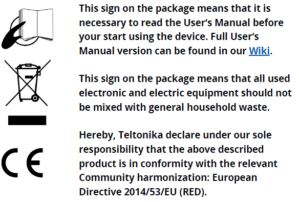
Certification and Approvals
- FMB202 EAC
- FMB202 REACH
- FMB202 Declaration of IMEI assignment
- FMB202 CE / RED
- FMB202 E-Mark
- FMB202 RoHS
- FMB202 Declaration of device operation temperature
Warranty
TELTONIKA guarantees its products to be free of any manufacturing defects for a period of 24 months. With additional agreement we can agree on a different warranty period, for more detailed information please contact our sales manager.
Contact us teltonika.lt/company/contacts
All batteries carry a reduced 6 month warranty period.If a product should fail within this specific warranty time, the product can be:
- Repaired
- Replaced with a new product
- Replaced with an equivalent repaired product fulfilling the same functionality
- TELTONIKA can also repair products that are out of warranty at an agreed cost.
Warranty Disclaimer
TELTONIKA PRODUCTS ARE INTENDED TO BE USED BY PERSONS WITH TRAINING AND EXPERIENCE. ANY OTHER USE RENDERS THE LIMITED WARRANTIES EXPRESSED HEREIN AND ALL IMPLIED WARRANTIES NULL AND VOID AND SAME ARE HEREBY EXCLUDED. ALSO EXCLUDED FROM THIS LIMITED WARRANTY ARE ANY AND ALL INCIDENTAL OR CONSEQUENTIAL DAMAGES INCLUDING BUT NOT LIMITED TO, LOSS OF USE OR REVENUE, LOSS OF TIME, INCONVENIENCE OR ANY OTHER ECONOMIC LOSS.More information can be found at teltonika.lt/warranty-repair
References
[xyz-ips snippet=”download-snippet”]