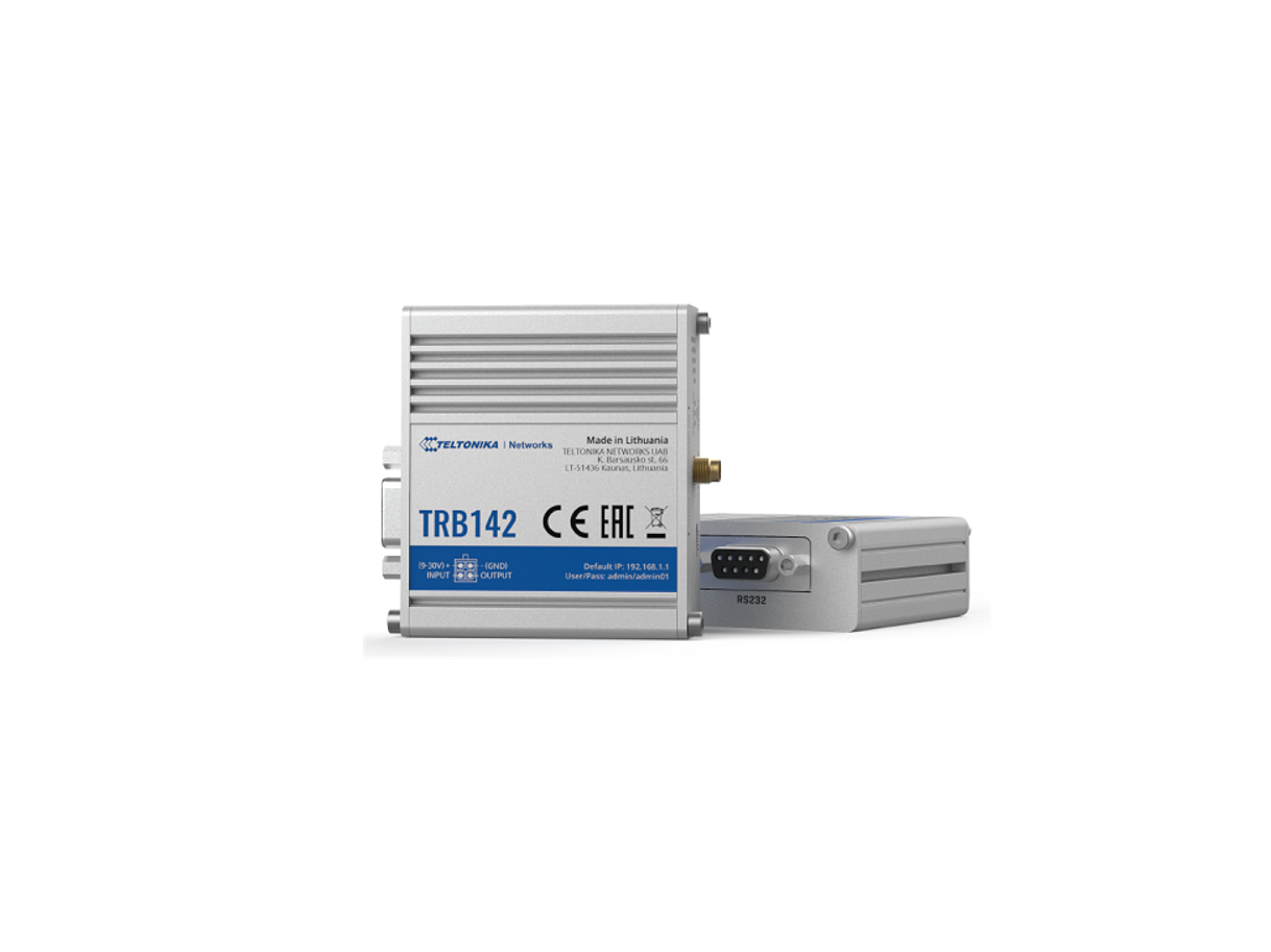
TELTONIKA RB142 Modem Antennas Compad Electronics User Guide

HARDWARE
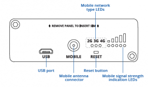
FRONT VIEW
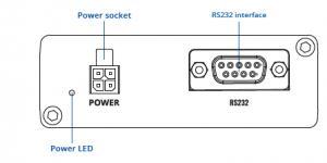
BACK VIEW
POWER SOCKET PINOUT

DB9 CONNECTOR PINOUT
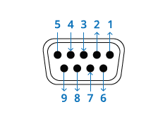
- Not used.
- Received Data (RX) – output.
- Transmitted data (TX) – input.
- Not used.
- Ground (GND).
- Not used.
- Request data to send (RTS) – input.
- Clear data to send (CTS) – output.
- Not used.
FEATURES

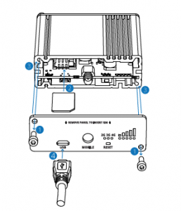
HARDWARE INSTALLATION
- Unscrew two back panel hex bolts and remove the back panel.
- Insert your SIM card into the SIM socket.
- Attach the panel and tighten the hex bolts.
- Attach the mobile antenna (max torque 0.4 N·m / 3.5 lbf·in) and connect the USB cable.
LOGIN TO DEVICE
- Power on the device and connect the USB cable to your
- Allow the gateway to boot up. This might take up to 30 seconds.
- Your computer’s OS should detect the USB device and install the
- To enter the gateway’s Web interface (WebUI), type http://192.168.2.1 into the URL field of your Internet browser.
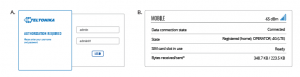
- Use login information shown in image A when prompted for
- After logging in pay attention to the Signal Strength indication displayed in the Mobile widget (image B). To maximize the cellular perfor- mance try adjusting the antennas or changing the location of your device to achieve the best signal
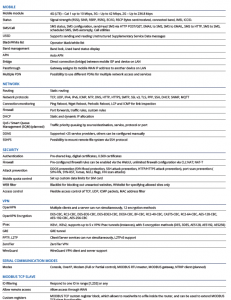
TECHNICAL INFORMATION
| Radio specifications | |
| RF technologies | 2G, 3G, 4G |
| Max RF power | 33 , 24 , 23 |
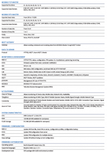
| Bundled accessories specifications* | |
| Power adapter | Input: , Output: 9VDC, 0.5A, 4-pin plug |
| Mobile antenna | 698~960/1710~2690 MHz, 50 Ω, VSWR<2, gain** 2 dBi, omnidirectional, SMA male connector |
WHAT’S IN THE BOX?
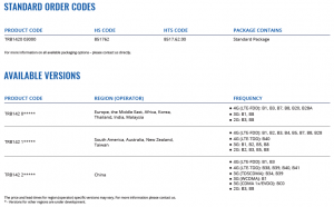
STANDARD PACKAGE CONTAINS*
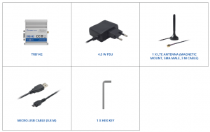
- TRB142
- 4.5 W PSU
- 1 x LTE antenna (magnetic mount, SMA male, 3 m cable)
- Micro-USB cable (0.8 m)
- 1 x hex key
- QSG (Quick Start Guide)
- RMS flyer
- Packaging box
TRB142 SPATIAL MEASUREMENTS & WEIGHT
MAIN MEASUREMENTSW x H x D dimensions for TRB142Device housing*:Box:74.5 x 25 x 64.4173 x 71 x 148
TOP VIEW
The figure below depicts the measurements of TRB142 and its components as seen from the top: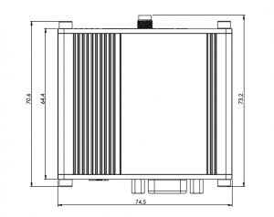
RIGHT VIEW
The figure below depicts the measurements of TRB142 and its components as seen from the right side: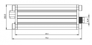
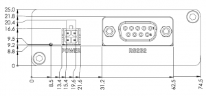
FRONT VIEW
The figure below depicts the measurements of TRB142 and its components as seen from the front:
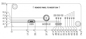
REAR VIEW
The figure below depicts the measurements of TRB142 and its components as seen from the back:
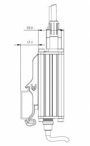
MOUNTING SPACE REQUIREMENTS
The figure below depicts an approximation of the device’s dimensions when cables and antennas are attached:

DIN RAIL
The scheme below depicts protrusion measurements of an attached DIN Rail:
Read More About This Manual & Download PDF:
[xyz-ips snippet=”download-snippet”]