![]()
![]() TRB255Quick Start Guide v1.3
TRB255Quick Start Guide v1.3
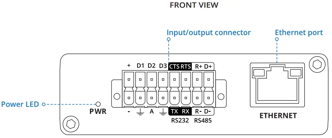
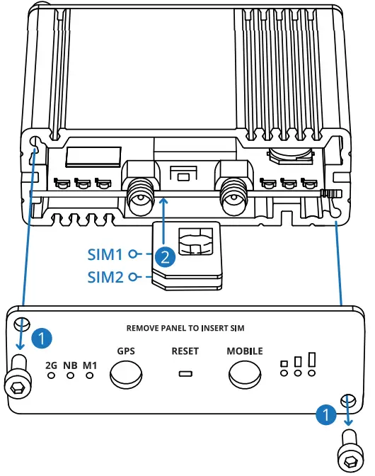
FRONT VIEW
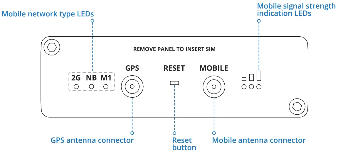
BACK VIEW
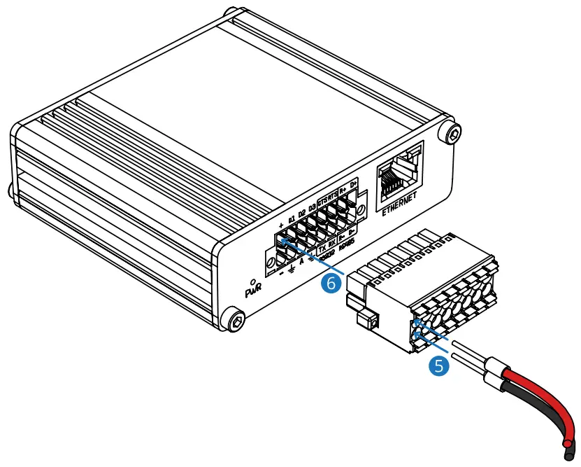
16 PIN CONNECTOR PINOUT
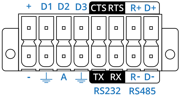
+ – 9-30 VDC positive power pinD1, D2, D3 – Configurable digital Input/Output pins. Open collector output, max output 30 V, 300 mA, or Digital input where 0-6 V detected as a logic low and 8-30 V – logic high.CTS – RS232 clear data to send pin (output).RTS – RS232 request data to send pin (input).R+ – RS485 receiver positive signal pin.D+ – RS485 driver positive signal pin.– – Negative/ground power pin.![]() – Ground pins for D1, D2, D3, A, RS232, and RS485.A – Analog input pin. Analog voltage range 0-30 V.TX – RS232 transmitted data (input).RX – RS232 received data (output).R- – RS485 receiver negative signal.D- – RS485 driver negative signal.
– Ground pins for D1, D2, D3, A, RS232, and RS485.A – Analog input pin. Analog voltage range 0-30 V.TX – RS232 transmitted data (input).RX – RS232 received data (output).R- – RS485 receiver negative signal.D- – RS485 driver negative signal.
HARDWARE INSTALLATION
- Unscrew two back panel hex bolts and remove the back panel.
- Insert your SIM card(s) into the SIM socket(s), which are located on the bottom side of the PCB.
- Attach the panel and tighten the hex bolts.
- Attach the mobile antenna (max torque 0.4 N·m / 3.5 lbf·in).

- Connect open PSU leads to 16 pin terminal block:a) red wire to top row first contact (+);b) black wire to bottom row first contact (-).
- Connect the 16 pin terminal block to the gateway 16 pin connector and plug another end of the power adapter into a power outlet.
DEVICE CONFIGURATION
- Power on the device and connect the Ethernet cable to your computer.
- Allow the gateway to boot up. This might take up to 60 seconds.
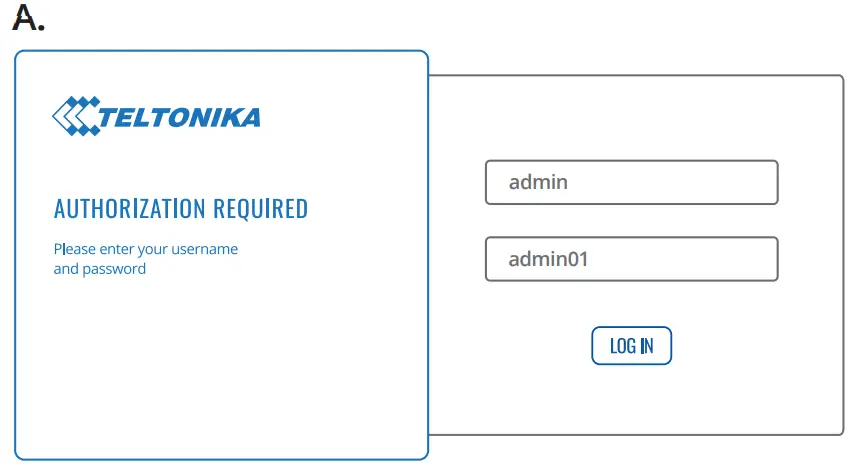
- To enter the gateway Web interface (WebUI), type http://192.168.1.1 into the URL field of your Internet browser.
- Use login information shown in image A when prompted for authentication.
- After you log in, you will be prompted to change your password for security reasons. The new password must contain at least 8 characters, including at least one uppercase letter, one lowercase letter, and one digit. This step is mandatory, and you will not be able to interact with the gateway WebUI until you change the password.
- When you change the gateway password, the Configuration Wizard will start. The Configuration Wizard is a tool used to set up some of the gateway’s main operating parameters.
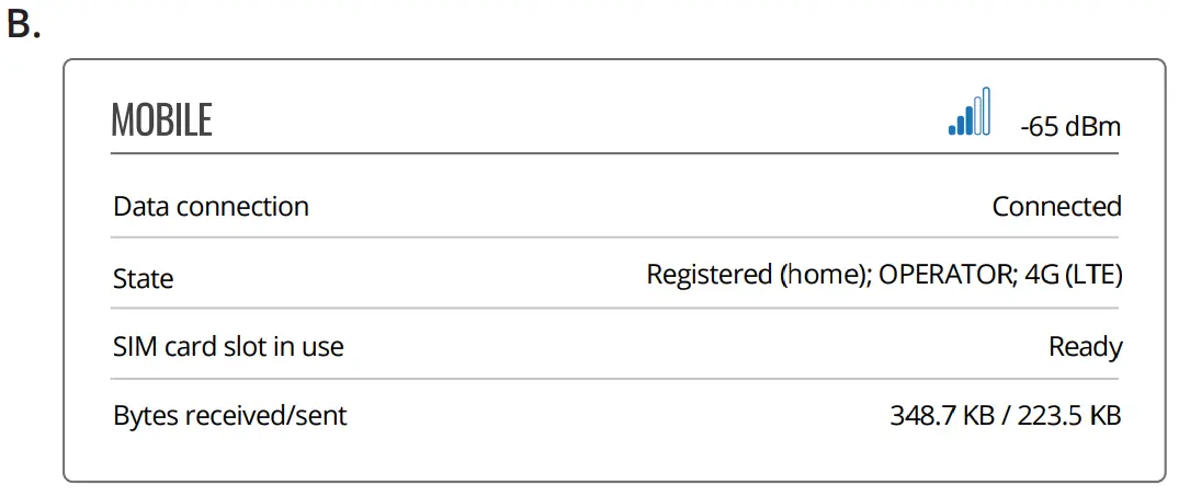
- Go to the Overview page and pay attention to the Signal Strength indication (image B). To maximize the cellular performance try adjusting the antennas or changing the location of your device to achieve the best signal conditions.
 |
 |
TECHNICAL INFORMATION
|
Radio specifications |
|
| RF technologies | EGPRS, NB-loT, LTE (Cat-M1), GNSS |
| Max RF power | 33 , 23 |
|
Bundled accessories specifications* |
|
| Power adapter | Input: 0.4 VAC, output: 9 VDC, 1 A, connected to 16 pin terminal block |
| Mobile antenna | 698-960 / 1710-2690 MHz, 50 0, VSWR < 3, gain** 3 dBi, omnidirectional, SMA male connector |
| GNSS antenna | 1575.42-1602 MHz, 2.2-5 VDC, VSWR < 1.5, gain** 28 dB (typ.), RHCP polarization, SMA male connector |
SAFETY INFORMATION
TRB255 gateway must be used in compliance with any and all applicable national and international laws and with any special restrictions regulating the utilization of the communication module in prescribed applications and environments.
Hereby, TELTONIKA declares that this TRB255 is in compliance with the essential requirements and other relevant provisions ofDirective RED.
The full text of the EU declaration of conformity is available at the followingInternet address: https://wiki.teltonika-networks.com/view/TRB255_CE/RED
Instruction Manual: Connect the power adapter to turn on the device. Open 192.168.1.1 in your web browser to configure it. More information on https://wiki.teltonika-networks.com/For more information visit www.teltonika-networks.com
![]()
![]()
wiki knowledge basehttps://wiki.teltonika-networks.com/

 This sign means that all used electronic andelectric equipment should not be mixed with general household waste. This sign means that all used electronic andelectric equipment should not be mixed with general household waste. |
www.teltonika-networks.com©2021 Teltonika Networks
References
[xyz-ips snippet=”download-snippet”]