
Minoston™ Z-Wave™ Meter Plug User Manual
Federal Communications Commission (FCC) Statement
FCC Caution: Any changes or modifications not expressly approved by the party responsible for compliance could void the user’s authority to operate this equipment.
This device complies with Part 15 of the FCC Rules. Operation is subject to the following two conditions: (1) This device may not cause harmful interference, and (2) this device must accept any interference received, including interference that may cause undesired operation.
NOTE: This equipment has been tested and found to comply with the limits for a Class B digital device, pursuant to Part 15 of the FCC Rules. These limits are designed to provide reasonable protection against harmful interference in a residential installation. This equipment generates, uses and can radiate radio frequency energy and, if not installed and used in accordance with the instructions, may caus harmful interference to radio communications. However, there is no guarantee that interference will not occur in a particular installation. If this equipment does cause harmful interference to radio or television reception, which can be determined by turning the equipment off and on,the user is encouraged to try to correct the interference by one or more of the following measures: Reorient or relocate the receiving antenna. Increase the separation between the equipment and receiver. Connect the equipment into an outlet on a circuit different from that to which the receiver is connected. Consult the dealer or an experienced radio/TV technician for help. This equipment should be installed and operated with minimum distance 20cm between the radiator and your body.
IC Caution:
This device complies with Industry Canada licence-exempt RSS standard(s). Operation is subject to the following two conditions: (1) this device may not cause interference, and (2) this device must accept any interference, including interference that may cause undesired operation of the device.
WARRANTY
Minoston Products warrants this product to be free from manufacturing defects for a period of two years from the original date of consumer purchase. This warranty is limited to the repair or replacement of this product only and does not extend to consequential or incidental damage to other products that may be used with this product.
This warranty is in lieu of all other warranties, expressed or implied. Some states do not allow limitations on how long an implied warranty lasts or permit the exclusion or limitation of incidental or consequential damage, so the above limitations may not apply to you.
This warranty gives you specific rights, and you may also have other rights which vary from state to state. if the unit should prove defective within the warranty period.
SPECIFICATIONS
Model:MP21ZPPower: 120 VAC, 60 Hz.Signal (Frequency): 908.42 MHZ.Maximum load for outlet 10A, 1200W ResistiveMaximum load for the Z-Wave™ controlled outlet: 600W Incandescent, ½ HP Motor or 1200W ResistiveRange: Up to 100 feet line of sight between the Wireless Control and the closest Z-Wave™ receiver module.Operating Temperature Range: 32-104° F (0-40° C)Specifications subject to change without notice due to continuing product improvement.Website:www.nie-tech.com
WARNING
RISK OF FIRERISK OF ELECTRICAL SHOCKRISK OF BURNSCONTROLLING APPLIANCES: EXERCISE EXTREME CAUTION WHEN USING Z-Wave™ DEVICES TO CONTROL APPLIANCES. OPERATION OF THE Z-Wave™ DEVICE MAY BE IN A DIFFERENT ROOM THAN THE CONTROLLED APPLIANCE, ALSO ANUNINTENTIONAL ACTIVATION MAY OCCUR IF THE WRONG BUTTON ON THE REMOTE IS PRESSED. Z-Wave™ DEVICES MAY AUTOMATICALLY BE POWERED ON DUE TO TIMED EVENT PROGRAMMING. DEPENDING UPON THE APPLIANCE, THESE UNATTENDED OR UNINTENTIONAL OPERATIONS COULD POSSIBLY RESULT IN A HAZARDOUS CONDITION. FOR THESE REASONS, WE RECOMMEND DO NOT RETURN THIS PRODUCT TO THE STORE
THE FOLLOWING:DO NOT USE Z-Wave™ DEVICES TO CONTROL ELECTRIC HEATERS OR ANY OTHER APPLIANCES WHICH MAY PRESENT A HAZARDOUS CONDITION DUE TO UNATTENDED OR UNINTENTIONAL OR AUTOMATIC POWER ON CONTROL
Introduction:
The MP21ZP is a Z-Wave™ enabled device and is fully compatible with any Z-Wave Plus™ enabled network. Each module is designed to act as a repeater,which will re-transmit a radio frequency (RF) signal by routing the around obstacles and radio dead spots to ensure that the signal is received at its intended destination. MP21ZP is a security enabled Z-Wave Plus™ device. A security Enabled Z-Wave Plus™ Controller must be used in order to fully utilize This product can be operated in any Z-Wave network with other Z-Wave certified devices from other manufacturers. All mains operated nodes within the network will act as repeaters regardless of vendor to increase reliability of the network.”
Key Features:
—Remote ON/OFF control via the Z-Wave™ controller—Manual ON/OFF control with the front panel push button—Support Association Group and Auto Report switch status—Support 5V 2A USB Charging—Support Z-Wave™ Range Test Tool—Support firmware upgrades via Over-the-air (
Product Overview:
A) AC plugB) Z-Wave™ controlled outletC) ON/OFF/PROG Push button/ Status LED
Key Function Description
Function 1: Press button one times to turn the outlet1 ON or OFFFunction 2: Press button three times quickly to ADD and REMOVEFunction 3: Press and hold button for 6-8 seconds to Z-Wave™ Range test toolFunction 4: Press the button twice quickly and then press and hold the button 10S.device will reset (Node:Please use this procedure only when the network primary controller is missing or otherwise inoperable)Function 5: Press button six times quickly to Change Parameter 17 Value(circulate)
LED Indicate Description
- LED Indicate Power MeterWhite = Plug is offDark Blue = 0 – 200 WCyan = 200 – 400 WGreen = 400 – 600 WOrange = 600 – 800 WRed = 800 – 1000 WPurple = 1000 – 1200 WPurple blink = over 1200 W
- LED Indicate Z-Wave™ Range Test ToolSolid Green = direct communication with the primary controller is stableFlashing green = direct communication with the primary controller, but the signal is not goodSolid orange = communication with the primary controller via repeater nodes, the signal is stableFlashing orange = communication with the primary controller via repeater nodes, but the signal is not goodSolid red = communication with the primary controller has failed
Z-Wave™ Remote Control
ADD or Remove the MP21ZP from the existing Z-Wave™ home control network with your primary controller.—Refer to your primary controller instructions to process the inclusion / exclusion setup procedure.—When prompted by your primary controller, click the PROG button Three times in one second.Include MP21ZP to/from a Z-Wave™ Gateway with supporting Security.The MP21ZP can support the Primary Controller that implemented theNotice: Including a node ID allocated by Z-Wave™TM Controller means “Add” or “Inclusion”. Excluding a node ID allocated by Z-Wave™TM Controller means “Remove” or “Exclusion”.
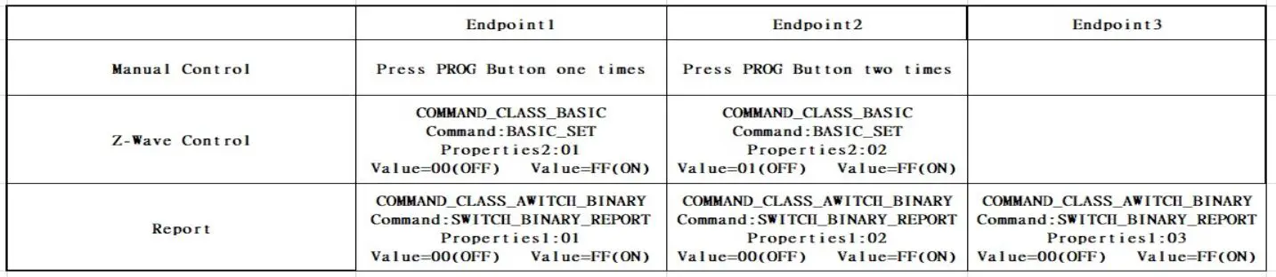
Z-Wave™ MULTI_CHANNEL
MP21ZP is multi channel device,It has three endpoints. Outlet-1 is Endpoint1, outlet-2 is Endpoint2. USB is Endpont3.MP21ZP Endpoint1 / Endpoint2 Device TypeGeneric Device Class: GENERIC_TYPE_SWITCH_BINARYSpecific Device Class: SPECIFIC_TYPE_POWER_SWITCH_BINARY
Z-Wave™ protocol Command Class Node Info
COMMAND_CLASS_ZWAVEPLUS_INFO,COMMAND_CLASS_SWITCH_BINARY,COMMAND_CLASS_ASSOCIATION,COMMAND_CLASS_MULTI_CHANNEL_ASSOCIATIONCOMMAND_CLASS_ASSOCIATION_GRP_INFO,COMMAND_CLASS_TRANSPORT_SERVICECOMMAND_CLASS_VERSION,COMMAND_CLASS_MANUFACTURER_SPECIFIC,COMMAND_CLASS_DEVICE_RESET_LOCALLY,COMMAND_CLASS_POWERLEVEL,COMMAND_CLASS_CONFIGURATION,COMMAND_CLASS_NOTIFICATIONCOMMAND_CLASS_METERCOMMAND_CLASS_SECURITY_2,COMMAND_CLASS_MULTI_CHANNELCOMMAND_CLASS_SUPERVISIONCOMMAND_CLASS_FIRMWARE_UPDATE_MD
The Below listed Command Class are all supported the Security S2
COMMAND_CLASS_VERSION,COMMAND_CLASS_SWITCH_BINARY,COMMAND_CLASS_ASSOCIATION,COMMAND_CLASS_MULTI_CHANNEL_ASSOCIATIONCOMMAND_CLASS_ASSOCIATION_GRP_INFO,COMMAND_CLASS_MULTI_CHANNELCOMMAND_CLASS_MANUFACTURER_SPECIFIC,COMMAND_CLASS_DEVICE_RESET_LOCALLY,COMMAND_CLASS_POWERLEVEL,COMMAND_CLASS_CONFIGURATION,COMMAND_CLASS_NOTIFICATIONCOMMAND_CLASS_METERCOMMAND_CLASS_FIRMWARE_UPDATE_MD
MP21ZP protocol Endpoint 1
Full Command Class Node Info
COMMAND_CLASS_ZWAVEPLUS_INFO,COMMAND_CLASS_ASSOCIATION,COMMAND_CLASS_ASSOCIATION_GRP_INFO,COMMAND_CLASS_MULTI_CHANNEL_ASSOCIATIONCOMMAND_CLASS_SWITCH_BINARY,COMMAND_CLASS_METERCOMMAND_CLASS_SUPERVISION,COMMAND_CLASS_SECURITY_2
The Below listed Command Class are all supported the Security S2
COMMAND_CLASS_ASSOCIATION,COMMAND_CLASS_ASSOCIATION_GRP_INFO,COMMAND_CLASS_MULTI_CHANNEL_ASSOCIATIONCOMMAND_CLASS_SWITCH_BINARY,COMMAND_CLASS_METER
MP21ZP protocol Endpoint 2
Full Command Class Node Info
COMMAND_CLASS_ZWAVEPLUS_INFO,COMMAND_CLASS_ASSOCIATION,COMMAND_CLASS_ASSOCIATION_GRP_INFO,COMMAND_CLASS_MULTI_CHANNEL_ASSOCIATIONCOMMAND_CLASS_SWITCH_BINARY,COMMAND_CLASS_METER_V4,COMMAND_CLASS_SUPERVISION,COMMAND_CLASS_SECURITY_2
The Below listed Command Class are all supported the Security S2
COMMAND_CLASS_ASSOCIATION,COMMAND_CLASS_ASSOCIATION_GRP_INFO,COMMAND_CLASS_MULTI_CHANNEL_ASSOCIATIONCOMMAND_CLASS_SWITCH_BINARY,COMMAND_CLASS_METER,
MP21ZP protocol Endpoint 3
Full Command Class Node Info
COMMAND_CLASS_ZWAVEPLUS_INFO,COMMAND_CLASS_ASSOCIATION,COMMAND_CLASS_ASSOCIATION_GRP_INFO,COMMAND_CLASS_MULTI_CHANNEL_ASSOCIATION,COMMAND_CLASS_SWITCH_BINARY,COMMAND_CLASS_SUPERVISION,COMMAND_CLASS_SECURITY_2
The Below listed Command Class are all supported the Security S2
COMMAND_CLASS_ASSOCIATION,COMMAND_CLASS_ASSOCIATION_GRP_INFO,COMMAND_CLASS_MULTI_CHANNEL_ASSOCIATION,COMMAND_CLASS_SWITCH_BINARY
Z-Wave™ Configuration Parameters
You may use the below configuration parameters to change settings of the corresponding functionality.
1:Restores state after power failureParamter No: 1(0x01) Size:1 Byte Value: 00(default) The state before a power outage.Value: 01 outlet onValue: 02 outlet off2:Power Wattage Report Value Threshold(Wattage) Value Scope :0—-65535WParamter No: 2(0x02) Size:4 Byte Value: xx xx xx xx (Default 10W)Value: 00 00 Disabled3:Power Wattage Report Frequency (Timer) Value Scope :30—-2678400SParamter No: 3(0x03) Size:4 Byte Value: xx xx xx xx (Default 30S)
4:Energy (kWh) Report Frequency (Timer) Value Scope :30—-2678400SParamter No: 4(0x04) Size:4 Byte Value: xx xx xx xx (Default 300S)5:Voltage (V) Report Frequency (Timer) Value Scope :30—-2678400SParamter No: 5(0x05) Size:4 Byte Value: xx xx xx xx (Default 300S)6:Electricity (A) Report Frequency (Timer) Value Scope :30—-2678400SParamter No: 6(0x06) Size:4 Byte Value: xx xx xx xx (Default 300S)7:Overload Protection (Current) Value Scope :1—-16AParamter No: 7(0x07) Size:1 Byte Value: xx (Default 13A)8:Endpoint1 Enable Auto Turn-OFF TimerParamter No: 8(0x08) Size:1 Byte Value=0 Auto Turn-OFF Timer Disabled (default);Value=1 Auto Turn-OFF Timer Enabled9:Endpoint1 Count Down Configuration(Turn off the output by time)Paramter No: 9(0x09) Size:4 Byte Value: xx xx Turn off OutputValue Scope :1—-65535Minutes (default:60M)10:Endpoint1 Enable Auto Turn-ON TimerParamter No: 10(0x0A) Size:1 Byte Value=0 Auto Turn-ON Timer Disabled (default);Value=1 Auto Turn-ON Timer Enabled11:Endpoint1 Count Down Configuration(Turn on the output by time)Paramter No: 11(0x0B) Size:4 Byte Value: xx xx xx xx Turn off OutputValue Scope :1—-65535Minutes (default:60M)12:Endpoint2 Enable Auto Turn-OFF TimerParamter No: 12(0x0C) Size:1 Byte Value=0 Auto Turn-OFF Timer Disabled (default);Value=1 Auto Turn-OFF Timer Enabled13:Endpoint2 Count Down Configuration(Turn off the output by time)Paramter No: 13(0x0D) Size:4 Byte Value: xx xx xx xx Turn off OutputValue Scope :1—-65535Minutes (default:60M)14:Endpoint2 Enable Auto Turn-ON TimerParamter No: 14(0x0E) Size:1 Byte Value=0 Auto Turn-ON Timer Disabled (default);Value=1 Auto Turn-ON Timer Enabled15:Endpoint2 Count Down Configuration(Turn on the output by time)Paramter No: 15(0x0F) Size:4 Byte Value: xx xx xx xx Turn off OutputValue Scope :1—-65535Minutes (default:60M)16:Manual ControlParamter No: 16(0x10) Size:1 Byte Value=0 Manual Control DisabledValue=1 Manual Control Enabled (default);17:Status LED ConfigurationParamter No: 17(0x11) Size:1 Byte (default:Value=01 )Value: 00 LED indicator will display power consumption whenever the device is plugged inValue: 01 LED indicator will display power consumption whenever the device is ON in and will turn off when the plug is OFFValue: 02 LED indicator will display the level of power consumption for 5 seconds only whenever the device is turned onValue: 03 Always OFF
Support for Association Groups
MP21ZP supports 3 association groups. Group 1 support 1 node ID,Group 2–3 Support maximum of 5 node ID’s
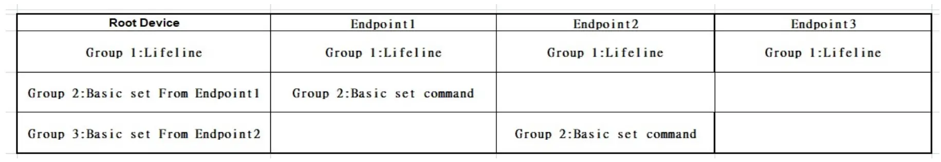
Association group_1:Z-Wave Plus™ LifelineAssociation group_1 is default to associate with the primary controller (Gateway/Hub/Controller) for MP21ZP Status change report,1. MP21ZP will trigger AUTO report function if the Switch status had been changed.Association group_2:basic set commandWhen the output of the MP21ZP Enpoint1 socket is changed, On (0xFF) or Off (0x00)orOverload, The MP21ZP will automatically send out a related basic set command. On (0xFF) or Off (0x00) to its associated group.Association group_3:basic set commandWhen the output of the MP21ZP Enpoint2 socket is changed, On (0xFF) or Off (0x00)orOverload, The MP21ZP will automatically send out a related basic set command. On (0xFF) or Off (0x00) to its associated group.
Support for Overload Protection
MP21ZP support Overload Protection ,When the MP21ZP load exceeds the overload setting value, the overload signal is sent out Notification Type : Overload 0x08 . Event :Overload detected 0x08
Restoring Factory Defaults
report this adMP21ZP is removed from the network and will be restored to the factory setting All Configuration Parameters values and Association information will be restored to factory default settings and excluded from the network.Remark : All the setting and data will be permanently deleted.Please use this procedure only when the network primary controller is missing or otherwise inoperable.
References
[xyz-ips snippet=”download-snippet”]