Category: teltonika
-

TELTONIKA Easy OBDII Tracker FMB003 User Manual
FMB003Easy OBDII tracker Quick Manualv1.2 Know your device Figure 1 FMB003 device view Pinout Table 1 OBDII pinout PIN NUMBER PIN NAME DESCRIPTION 2 PWM_BUS+/VPW 4 GND (-) Ground 5 GND (-) Ground 6 CAN_H CAN high 7 K-Line 14 CAN_L CAN low 15 L-Line 16 VCC (12 – 30)V DC(+) Power supply (+12-30 V…
-

TELTONIKA FMB002 Easy OBDII Tracker with Bluetooth User Manual
-

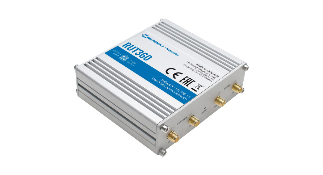
TELTONIKA RUT360 LTE Industrial Router User Guide
RUT360Quick Start Guide v1.1 Wiki knowledge base https://wiki.teltonika-networks.com/ https://wiki.teltonika-networks.com/ FRONT VIEW BACK VIEW POWER SOCKET PINOUT I/O: programmable Input/Output pins (Open Collector output max 30 V, 300 mA or Digital input where 0-6 V detected as a logic low and 8-30 V – logic high). HARDWARE INSTALLATION Push the SIM holder button with the SIM…
-

TELTONIKA TSW110 Unmanaged Switch User Guide
TSW110Quick Start Guide v1.1 Wiki knowledge base https://wiki.teltonika-networks.com/ FRONT VIEW BACK VIEW POWER SOCKET PINOUT RJ45 LED MEANING TECHNICAL INFORMATION Technical specifications Input voltage range 9 – 30 VDC Max power consumption <1.8 W Bundled accessories specifications* Power adapter Input 0.4 A @100-240 VAC, Output 9 VDC, 1 A, 4 pin plug * Order…
-

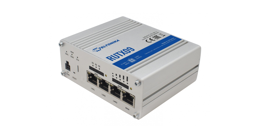
TELTONIKA RUTX09 LTE-A CAT6 Cellular IoT Dual SIM Router User Guide
NetworksQuick Start Guide v2.3Wiki knowledge basehttps://wiki.teltonika-networks.com/ https://wiki.teltonika-networks.com/ FRONT VIEW BACK VIEW POWER SOCKET PINOUT HARDWARE INSTALLATION Pull out the SIM needle from the front panel of the router. Push the SIM holder button with the SIM needle. Pull out the SIM holder. Insert your SIM card into the SIM holder. Slide the SIM holder back…
-

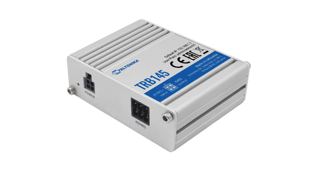
TELTONIKA TRB145 4G LTE RS485 Gateway User Guide
NetworksTRB145Quick Start Guide v2.4 Wiki knowledge basehttps://wiki.teltonika-networks.com/https://wiki.teltonika-networks.com/ FRONT VIEW BACK VIEW DB9 CONNECTOR PINOUT Driver negative signal (D-). Receiver negative signal (R-). Ground (GND). Driver positive (D+). Receiver positive signal (R+). Power input 9-30 VDC (Vin). POWER SOCKET PINOUT HARDWARE INSTALLATION Unscrew two back panel hex bolts. Remove the back panel. Insert your SIM card…
-

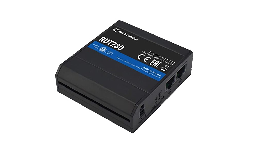
TELTONIKA RUT230 Wifi Router- Modem User Guide
TELTONIKA RUT230 Wifi Router- Modem User Guide Product Overview FRONT VIEW BACK VIEW POWER SOCKET PINOUT HARDWARE INSTALLATION Push the SIM holder button with the SIM needle. Pull out the SIM holder. Insert your SIM card into the SIM holder. Slide the SIM holder back into the router. Attach all antennas. Connect the power adapter…
-

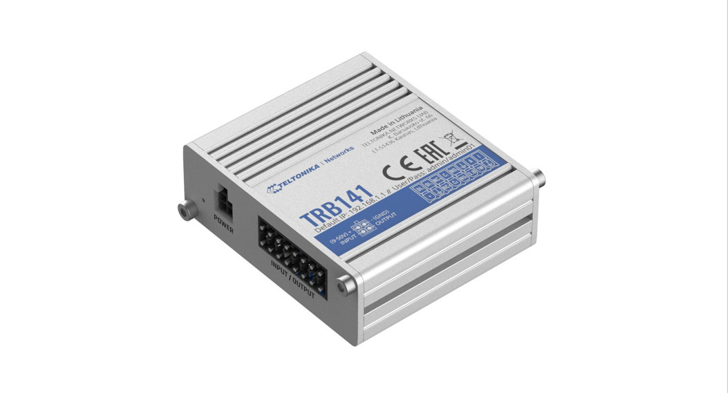
TELTONIKA TRB141 Gateway User Guide
NetworksQuick Start Guide v1.3Wiki knowledge basehttps://wiki.teltonika-networks.com/https://scnv.io/BbOw?qr=1 FRONT VIEWBACK VIEWINPUT/OUTPUT CONNECTOR PINOUTPOWER SOCKET PINOUT POWER SOCKET PINOUT Unscrew two back panel hex bolts and remove the back panel. Insert your SIM card into the SIM socket. Attach the panel and tighten the hex bolts. Attach the mobile antenna (max torque 0.4 N·m / 3.5 lbf·in). Connect…
-

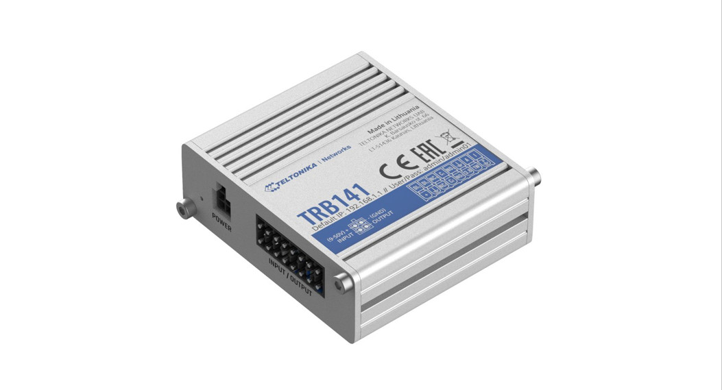
TELTONIKA TRB141 Gateway User Guide
NetworksQuick Start Guide v1.3Wiki knowledge basehttps://wiki.teltonika-networks.com/https://scnv.io/BbOw?qr=1 FRONT VIEWBACK VIEWINPUT/OUTPUT CONNECTOR PINOUTPOWER SOCKET PINOUT POWER SOCKET PINOUT Unscrew two back panel hex bolts and remove the back panel. Insert your SIM card into the SIM socket. Attach the panel and tighten the hex bolts. Attach the mobile antenna (max torque 0.4 N·m / 3.5 lbf·in). Connect…
-

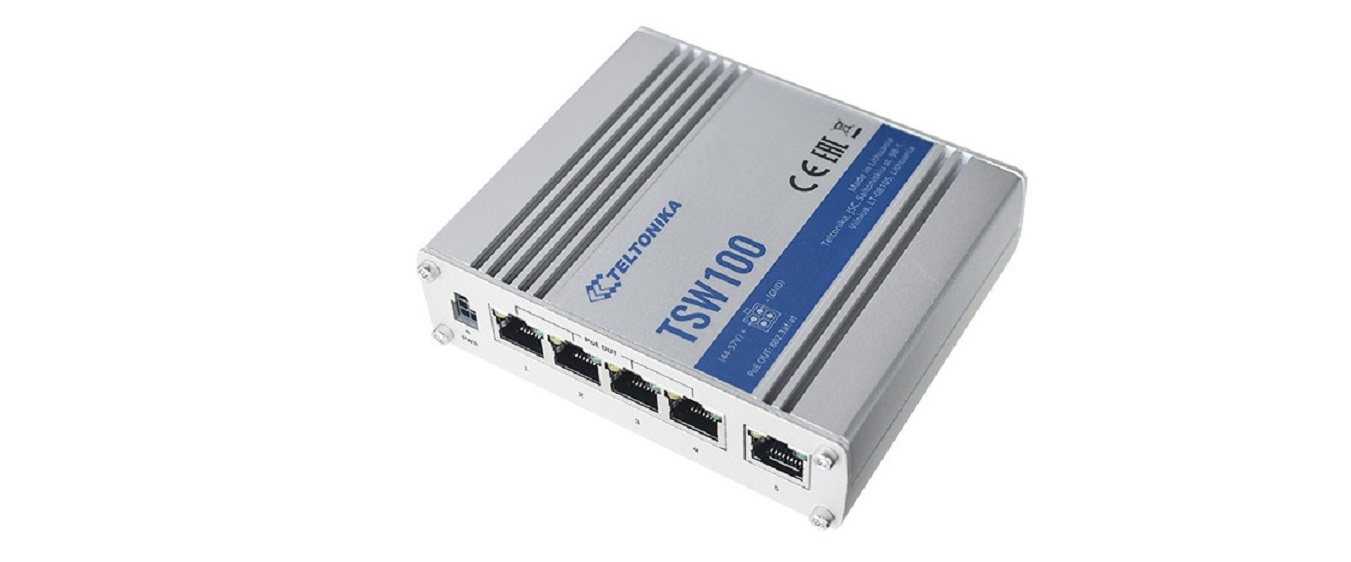
TELTONIKA TSW100 Ethernet Switch User Guide
TELTONIKA TSW100 Ethernet Switch User Guide FRONT VIEW BACK VIEW POWER SOCKET PINOUT RJ45 LED MEANING TECHNICAL INFORMATION Technical specificati ons Input voltage range* 7 – 58 VDC Max power consumption no PoE devices connected <9 W Max PoE power budget at PSE** 120 W Max Ethernet cable length 100 m Bundled accessories specifications*** Power…

